14 ADV100 • Quick installation guide - Specifications and connection
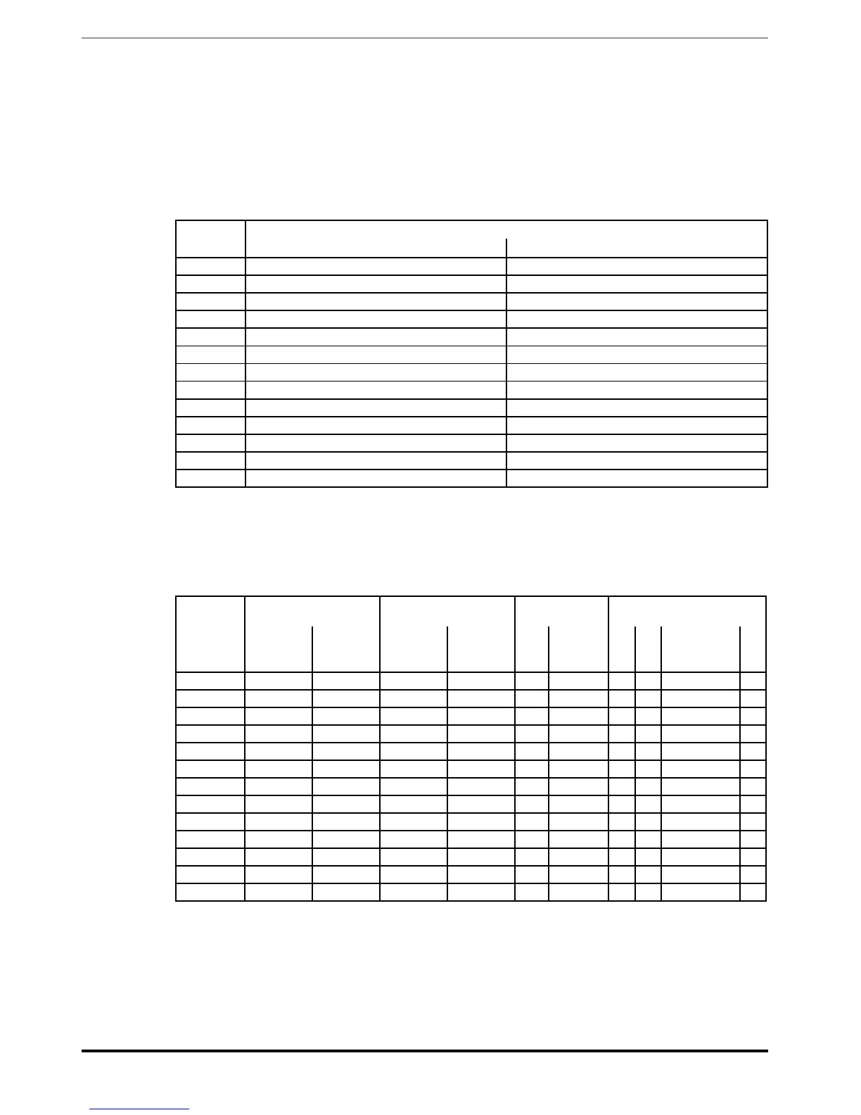
4.4 Input electrical data
Input voltage, Uln ���������������������� three-phase network 230 Vca (-15%) ... 500 Vca (+5%)
Power supply system �������������������� TT, TN with EMI filter, IT without EMI filter (no UL)
Maximum line voltage unbalance ����������� 3%
Input frequency ������������������������ 50/60 Hz, ± 2%
Overvoltage threshold ������������������� 820 Vcc
Undervoltage threshold ������������������ @ 480V = 470 Vcc ; @ 400V = 390 Vcc; @ 230V = 225 Vcc
Choke ������������������������������� Sizes 1...3: Optional (DC or AC), size 4 : integrated (DC)
Total harmonic distortion (THD) ����������� > 100% sizes 1040 ... 3220 (without choke)
< 50% sizes 4300 ... 5900 (with integrated choke)
Size effective input current in (@ in out)
@ 230 V@ 230 - 400 Vca (A)ac (A) @ 480 Vca (A)0 Vca (A)
1040 11 10
1055 16 14
2075 20 18
2110 28 26
3150 40 38
3185 47 44
3220 53 49
4300 53 50
4370 64 60
4450 74 71
5550 100 92
5750 143 135
5900 171 165
4.5 Output electrical data
Maximum output voltage U2 �������������� 0.98 x Uln (Uln = AC input voltage)
Maximum output frequency f2 ������������� 500 Hz
IGBT braking unit ���������������������� Standard internal (with external resistor); braking torque 150% MAX
Size In Rated output current
(fsw = default)
Pn mot (Recommended motor
power ,fSw = default)
fSw
Switching frequency
Derating factor
@Uln = 400Vca @Uln = 460Vca @Uln = 400Vca @Uln = 460Vca Default Higher Kv Kt Kf Kalt
(A) (A)
(kW) (Hp)
(1) (2) (3) (4)
1040 9,5 8,6 4 5 4 6, 8, 10, 12 0,9 0,9 0,85; 0,7; 0,6; 0,5 1,2
1055 13 11,7 5,5 7,5 4 6, 8, 10, 12 0,9 0,9 0,85; 0,7; 0,6; 0,5 1,2
2075 16,5 14,9 7,5 10 4 6, 8, 10, 12 0,9 0,9 0,85; 0,7; 0,6; 0,5 1,2
2110 23 20,7 11 15 4 6, 8, 10, 12 0,9 0,9 0,85; 0,7; 0,6; 0,5 1,2
3150 31 27,9 15 20 4 6, 8, 10, 12 0,9 0,9 0,85; 0,7; 0,6; 0,5 1,2
3185 38 34,2 18,5 25 4 6, 8, 10, 12 0,9 0,9 0,85; 0,7; 0,6; 0,5 1,2
3220 46 41,4 22 30 4 6, 8, 10, 12 0,9 0,9 0,85; 0,7; 0,6; 0,5 1,2
4300 62 55,8 30 40 4 6, 8, 10, 12 0,9 0,9 0,85; 0,7; 0,6; 0,5 1,2
4370 75 67,5 37 50 4 6, 8, 10, 12 0,9 0,9 0,85; 0,7; 0,6; 0,5 1,2
4450 87 78 45 60 4 6, 8 0,9 0,9 0,85; 0,7 1,2
5550 105 94,5 55 75 4 6, 8 0,9 0,9 0,85; 0,7 1,2
5750 150 135 75 100 4 6, 8 0,9 0,9 0,85; 0,7 1,2
5900 180 162 90 125 4 6, 8 0,9 0,9 0,85; 0,7 1,2
(1) Kv : Derating factor for mains voltage at 460Vac
(2) Kt : Derating factor for 50°C ambient temperature (1 % each °C above 40°C)
(3) Kf : Derating factor for higher switching frequency
(4) Kalt : Derating factor for installation at altitudes above 1000 meters a.s.l.. Value to be applied at each 100 m increase above 1000 m
I.e.: Altitude 2000 m, Kalt = 1,2 *10 = 12% di derating; In derated = (100 - 12) % = 88 % In
 Loading...


