ADV100 • Quick installation guide - Specifications and connection 43
Connection to a PC with RS232 port (not isolated)
The following are required for connection:
• a shielded cable (code 8S8F59) for connection to the RS232 PC port of the drive to the RS232 connector of the
PC, see gure 7.5.1-B.
Connection to a PC with USB port (not isolated)
The following are required for connection:
• an optional USB/RS232 adapter, code S5A20 (including the cable for USB connection)
• a shielded cable (code 8S8F59) for connection to the RS232 PC port of the drive to the USB/RS232 adapter, see
gure 7.5.1-C.
7.6 CAN interface
CANopen is a communication prole for CAL-based industrial systems (refer to the CANopen CAL-Base
COMMUNICATION PROFILE for Industrial Systems; CiA Draft Standard 301 Version 4.2 Date 13 February 2002 by
CAN in Automation e. V.).
The ADV100 can be requested with the interface for connection to CAN networks at the time of ordering
(ADV120-...-C models). The drive also implements the DS402 prole according to CANopen Device Prole Drives
and Motion Control v4.02 specications. The CAN protocol (ISO 11898) used is CAN2.0A with 11-bit identier. The
integrated CANopen interface has been developed as a Minimum Capability Device. Data are exchanged cyclically; the
master reads the data made available by the slaves and writes the reference data to the slaves.
The interface is provided with functional isolation (> 1 kV).
Connection is via the CAN (XC) connector and no power supply is required.
SIEIDrive
ADV100
SD Card
WARNING:
Risk of Electric Shock.
Capacitive voltages above 50V may
remain for 5 minutes after power is
disconnected.
AVERTISSEMENT:
Risque de décharge électrique.
Des tensions supérieures à 50V
peuvent subsister aux bornes des
condensateurs durant 5 minutes
après la coupure de l’alimentation.
Keypad PC
Connectors
CAN
L
Status LEDs
SH H
EN
CAN Error
Alarm
I Lim
CAN Run
Run
CAN connector (XC)
CAN LEDs
Terminal Name Function Cable cross-section
L CAN�L CAN�L bus line (low dominant)
0,2 ... 2.5 mm
2
AWG 26 ... 12
SH CAN�SHLD CAN shielding
H CAN�H CAN�H bus line (high dominant)
LEDs Meaning
CAN Run
(green)
CAN Err
(red)
Off Off Stop
On Off Pre-operational
On On Operational
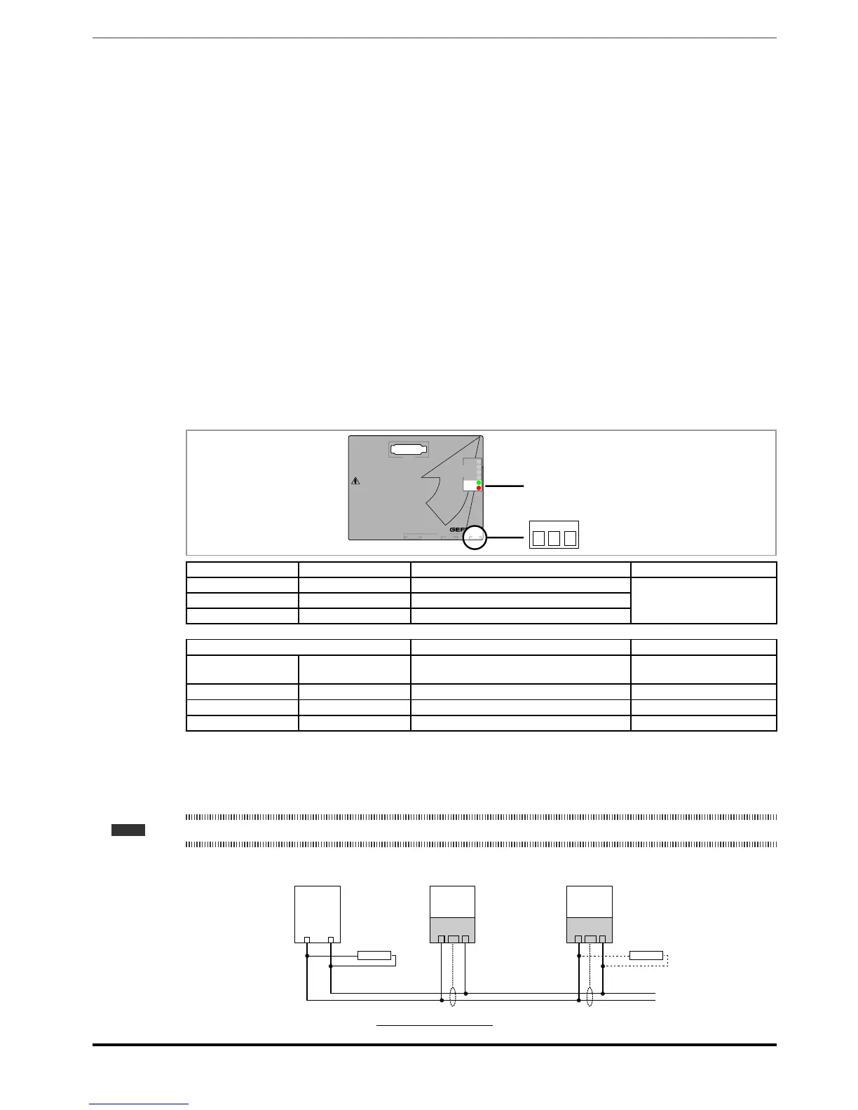
A shielded twin-pair (of the type described in the CANopen specications) must be used for connection to the bus, and
must be laid separately from the power cables, at a distance of at least 20 cm. Cable shielding must be grounded at
the two ends. If the cable shielding is grounded at different points of the system, use equipotential connection cables to
reduce the current ow between the drive and the CANbus master.
Note! As regards terminations: the first and last termination on the network must have a 120 ohm resistor between pins L and H.
CAN-H
MASTER
CANopen
120 ohm
L
ADV100
SH H
CAN (XC)
120 ohm
L
ADV100
SH H
CAN (XC)
CAN-L
Figure 7.6.1: CANbus connection
 Loading...


