ADV100 • Quick installation guide - Specifications and connection 29
7.1 Power section
7.1.1 Cable cross-sections
Size
Terminals: L1 - L2 - L3 - BR - C1 - C - D - U - V - W
Maximum cable cross-section
(flexible conductor)
Recommended
stripping
Recommended
terminal
Tightening
torque (min)
(mm
2
) AWG (mm) (mm) (Nm)
1040 4 10 10 None / pin 0,5 ... 0,6
1055 4 10 10 None / pin 0,5 ... 0,6
2075 6 8 10 None / pin 1,2 ... 1,5
2110 6 8 10 None / pin 1,2 ... 1,5
3150 16 6 14 None / pin 1,5 ... 1,7
3185 16 6 14 None / pin 1,5 ... 1,7
3220 16 6 14 None / pin 1,5 ... 1,7
Terminals: L1 - L2 - L3 - BR1 - BR2 - C - D - U - V - W
4300
35 2 18 None / pin 2,4 ... 4,5
4370
35 2 18 None / pin 2,4 ... 4,5
4450
35 2 18 None / pin 2,4 ... 4,5
5550
95 (BR1/BR2=50) 4/0 (BR1/BR2=1/0) 23 (BR1/BR2=27) None / pin 14 (BR1/BR2=10)
5750
95 4/0 23 None / pin 14
5900
95 4/0 23 None / pin 14
Note! The power terminal strip is extractable on all mechanical sizes.
Size
Terminals:
on structural work (PE1: line ground – PE2: motor ground)
Cable cross-section Lock screw diameter Recommended
terminal
Tightening torque (min)
(mm
2
) AWG (mm) (mm) (Nm)
1040 4 10 M5 Eyelet 6
1055 4 10 M5 Eyelet 6
2075 6 8 M5 Eyelet 6
2110 6 8 M5 Eyelet 6
3150 16 6 M5 Eyelet 6
3185 16 6 M5 Eyelet 6
3220 16 6 M5 Eyelet 6
4300 16 6 M5 Eyelet 6
4370 16 6 M5 Eyelet 6
4450 16 6 M5 Eyelet 6
5550 50 1/0 M6 Eyelet 10
5750 50 1/0 M6 Eyelet 10
5900 50 1/0 M6 Eyelet 10
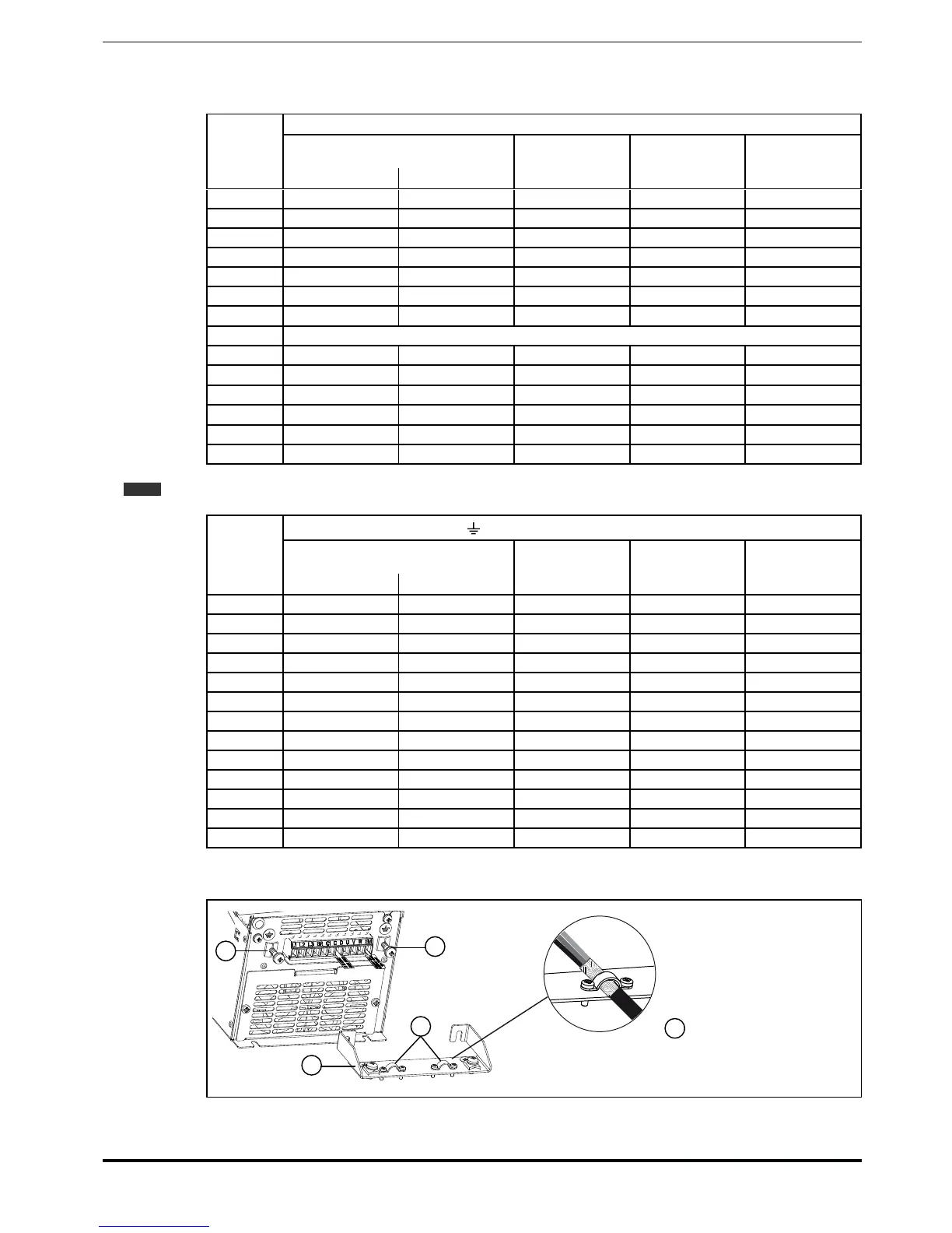
7.1.2 Connection of shielding (recommended)
B
B
A
C
A
Size Code Description
1-2 S72610 POWER SHIELD KIT
3 S72650 POWER SHIELD KIT
Loosen the two screws (B), put the metal support (A) (optional) in place and screw down tightly. Fasten the power
cable shield to the omega sections (C) as illustrated in the gure.

 Loading...


