ADV100 • Quick installation guide - Specifications and connection 45
7.9 Braking
There are various possible types of braking:
- Internal Braking Unit
- Injection of direct current from the Inverter into the motor (D.C. braking)
There are two essential differences between the two braking methods:
- A braking unit can be used for speed reduction (e.g.: from 1000 to 800 rpm), whereas D.C. braking can only be
usedfor braking to standstill.
- The energy in the drive is converted into heat in both cases. This conversion takes place in a braking resistor
encased in the braking unit. With D.C. braking, the energy is converted into heat in the motor itself, resulting in a
further rise in motor temperature.
7.9.1 Braking unit (standard internal)
Frequency-regulated asynchronous motors during hyper-synchronous or regenerative functioning behave as genera-
tors, recovering energy that ows through the inverter bridge, in the intermediate circuit as continuous current.
This leads to an increase in the intermediate circuit voltage.
Braking units (BU) are therefore used in order to prevent the DC voltage rising to an impermissible value. When used,
these activate a braking resistor that is connected in parallel to the capacitors of the intermediate circuit. The feedback
energy is converted to heat via the braking resistor (Rbr), thus providing very short deceleration times and restricted
four-quadrant operation.
ADV110-...-.BX and ADV120-...-.BX congurations include an internal braking unit.
E
3
M
_
R
BR
BU
U
ZK
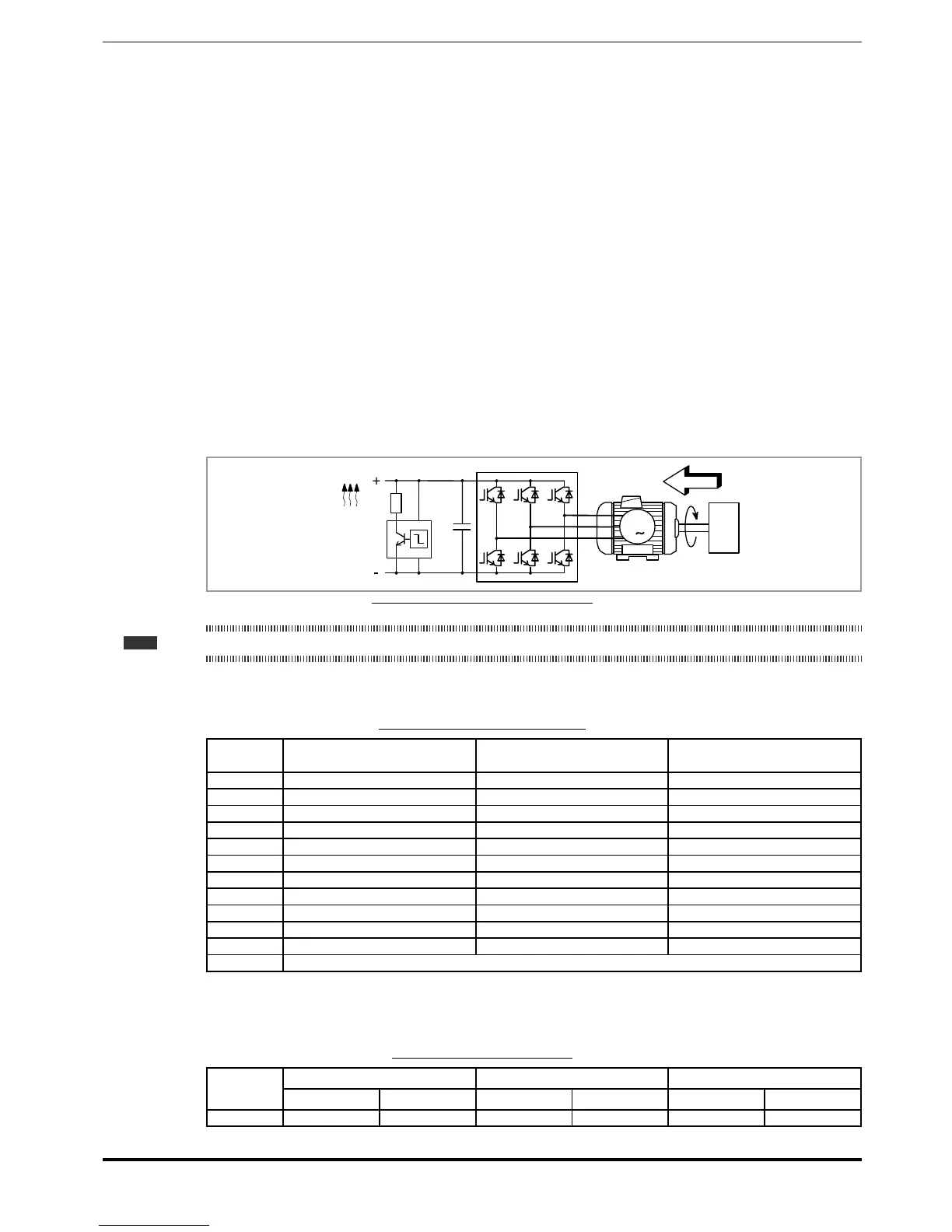
Figure 7.9.1: Operation with braking unit (circuit diagram)
Note! When the internal braking unit is present the protection must consist of fast-acting fuses! Follow the relative assembly instructions.
A twisted cable must be used for the connection of the braking resistor (terminals BR and C or BR1 and BR2). If the
resistor includes a thermal protection device (Klixon), this must be connected to the "External fault" input of the drive.
Table 7.9.1: Technical data of the internal braking unit
Size IrmS
(A)
Ipk
(A)
Rbr
(Ω)
1040 5,7 8 100
1055 8,5 12 67
2075 8,5 12 67
2110 15,5 22 36
3150 22 31 26
3185 37 53 15
3220 37 53 15
4300 57 80 10
4370 57 80 10
4450 76 107 7,5
5550 76 107 7,5
≥ 5750 External braking unit (BUy series, optional)
Irms Braking unit rated current, duty cycle = 50%
Ipk Peak current that can be delivered for max 60 seconds
Rbr Minimum braking resistance value
Table 7.9.2: Braking unit intervention threshold
Size
vbr @ 480 V vbr @ 400 V vbr @ 230V
ON
OFF
ON OFF ON OFF
1040 ... 5900 800 Vcc
790 Vcc
670 Vcc 660 Vcc 395 Vcc 385 Vcc

 Loading...


