ADV100 • Quick installation guide - Specifications and connection 63
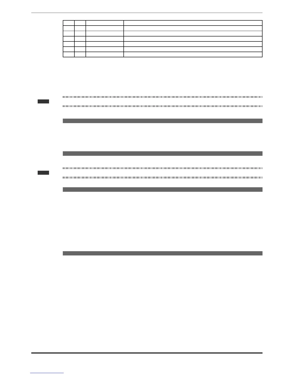
16.6 2010 Rated power Motor rated power
16.9 2022 Autotune rotation Self-tuning with motor rotating
16.10 2024 Autotune still Self-tuning with motor at stand-still or coupled to the load
5.24 680 Full scale speed Maximum speed setting
6.1 700 Acceleration time 0 Acceleration time 0
6.2 702 Deceleration time 0 Deceleration time 0
4.1 550 Save parameters Save parameters in the non-volatile memory
9.2 First customized start-up
In this section a startup test is performed, using a standard conguration, to check drive functioning and command con-
nections.
A programming sequence has to be run to achieve a rst simple customisation in order to be able to set the drive for
the requested application.
Note ! The main sections to be used, depending on the desired conguration, are described below.
• Typical connection diagrams
Auxiliary control circuits ������������������������������������� see chapter 7.4.2, figure 7.4.3
Typical connection diagram, connection through terminals strip �������� see chapter 7.4.2, figure 7.4.4/5
Potentials of the control section, Digital I/O PNP connection ����������� see chapter 7.4.1,
figure
7.4.1
Other inputs connections (NPN-PNP) ���������������������������� see chapter 7.4.1,
figure
7.4.2
• Digital inputs
The table on chapter 7.2.2 shows the default settings for the analog and digital inputs and outputs.
Note ! Digital input settings can only be edited from the Expert parameters, see chapter 8.5.2.
• Selecting the regulation mode
First set the regulation mode in the Regulation mode parameter (04 DRIVE CONFIG menu, PAR: 552) :
0 V/f control. This is the simplest and least advanced control mode. This mode can also be used to control several
motors connected in parallel using a single drive.
1 Open loop eld-oriented vector control (sensorless). In this mode, once the motor parameter self-tuning
procedure has been performed, it is possible to create a mathematical model on which to perform all the neces-
sary calculations in order to obtain high performance levels, especially high motor torque levels, even at very low
speeds without the use of feedback, and achieve signicant dynamic performance.
2 Closed loop eld-oriented vector control. This mode can be used to obtain maximum drive-motor efciency in
terms of speed precision, dynamic system response and motor torque regulation. It requires feedback by a digital
encoder keyed to the motor shaft and connected to the relative optional expansion card mounted in the drive.
• Selecting the type of reference
After setting the regulation mode, the source of the speed reference must be set in the Ramp ref 1 src parameter (05
REFERENCES menu, PAR: 610). This source can be selected from among those listed in the L_MLTREF selection list:
1 Analog input 1X mon parameter (PAR: 1600) to use the signal applied to terminals 1 – 2 of analog input 1 (14 -
ANALOG INPUTS menu).
2 Dig ramp ref 1 parameter (05 - REFERENCES menu, PAR: 600) to set a digital speed inside the drive.
3 Multi ref out mon parameter (07 - MULTI REFERENCE menu, PAR: 852) to select the digital speeds using the
digital inputs of the drive.
4 Mpot output mon parameter (08 - MOTOPOTENTIOMETER menu, PAR: 894) to use the internal motor poten-
tiometer of the drive. If sending the command from the operator keypad, to use the motor potentiometer function
enter the Mpot setpoint parameter (PAR: 870) modify mode and press the Up (▲) and Down (▼) keys.
5 Jog output mon parameter (09 - JOG FUNCTION menu, PAR: 920) to use one of the drive’s internal jog speeds.
Signals from expansion cards, the serial line or eldbus can also be set as speed references (see the detailed descrip-
tion of parameters).

 Loading...


