—————— TPD32-EV ——————
278
Inp absolute Theinputbehaviorcanbedeterminedwiththisparameter.
OFF Theinputquantityisprocessedwithitssign.
ON Theinputquantityisprocessedwithapositivesign(absolute
value).Itispossibletohaveapolaritychangewiththesigns
of Mul gain or Div gain.
In order to write SOURCE LINK (1/6) parameter or DESTINATION LINK (1/6) parameter it is neces-
sary to add to the parameter number the offset “8192”
Eg. RAMP REF 1 “44”
SOURCE LINK (1/2) = 44+8192 = 8236
note! TheLinksareexecutedwithanapproximatecycletimeof20ms.Theyarenotmainlyintended
tobeusedforregulationbuttoaccessorconnectparametersotherwisenotaccessible.The
useofLinksaccordingtotheparameterchosenasadestinationinvolvesaCPUoverhead
thatcanslowdownthekeypad/displayoperation.Checkthatthefunctionalitycorresponds
totheneedsbeforeplant-wideimplementation.
note! ThefollowingparameterscannotbeusedasadestinationofaLink:
- Allparameterswithonly“R”accesscode
- Allparameterswith“Z”accesscode
- Allparameterswith“C”accesscode
- Allthefollowing:
19
55
72
73
77
78
82
85
83
86
318
408
425
444
453
454
456
467
468
470
Sshapetconst
Controlword
Scaleinput1
Tunevalueinp1
Scaleinput2
Tunevalueinp2
Scaleinput3
Pword1
Tunevalueinp3
Password2
Overloadmode
Seranswerdelay
EnableOPT2
Prop.Filter
Armresistance
Arminductance
Fluxweakspeed
Fluxcurrentmax
Fluxcurrentmin
Undervoltage-Holdofftime
474
475
480
482
483
484
485
501
502
553
554
562
585
586
636
637
649
652
663
664
Fieldloss-Restarttime
Fieldloss-Holdofftime
Speedfbkloss-Holdofftime
Overvoltage-Holdofftime
Overvoltage-Restarttime
Link1-Source
Link1-Destination
Externalfault-Restarttime
Externalfault-Holdofftime
Link2-Source
Link2-Destination
Tachoscale
Overcurrent-Restarttime
Overcurrent-Holdofftime
Busloss-Holdofftime
Busloss-Restarttime
Refreshenc1
Refreshenc2
Sacctconst
Sdectconst
665
666
667
668
669
670
671
672
776
785
786
792
1012
1013
1014
1015
1042
1043
1044
Sacctconst0
Sdectconst0
Sacctconst1
Sdectconst1
Sacctconst2
Sdectconst2
Sacctconst3
Sdectconst3
PIcentralV1
PIbottomlim
PIDsource
Input1lter
Inertiaclter
Torqueconst
Inertia
Friction
Input1compare
Input1cperror
Input1cpdelay
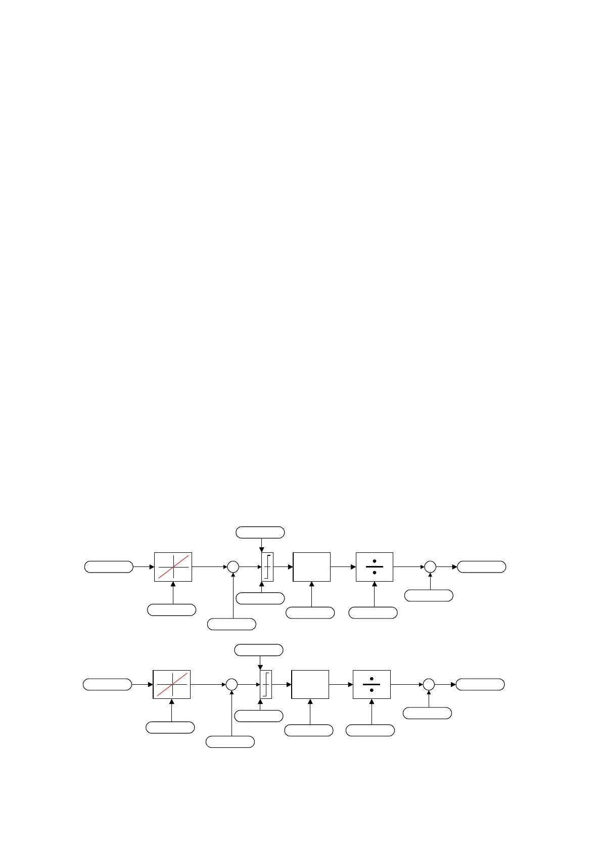
+
+
X
+
+
LINK 1
+
+
X
+
+
LINK 2
Source 1
0
Input absolute 1
Off
Input offset 1
0
Mul gain 1
1
Div gain 1
1
Output offset 1
0
Destination 1
0
Input min 1
0
Input max 1
0
Source 2
0
Input absolute 2
Off
Input offset 2
0
Mul gain 2
1
Div gain 2
1
Output offset 2
0
Destination 2
0
Input min 2
0
Input max 2
0
Figure 6.15.4.1: Structure of the signal adaptation
 Loading...


