—————— TPD32-EV ——————
484
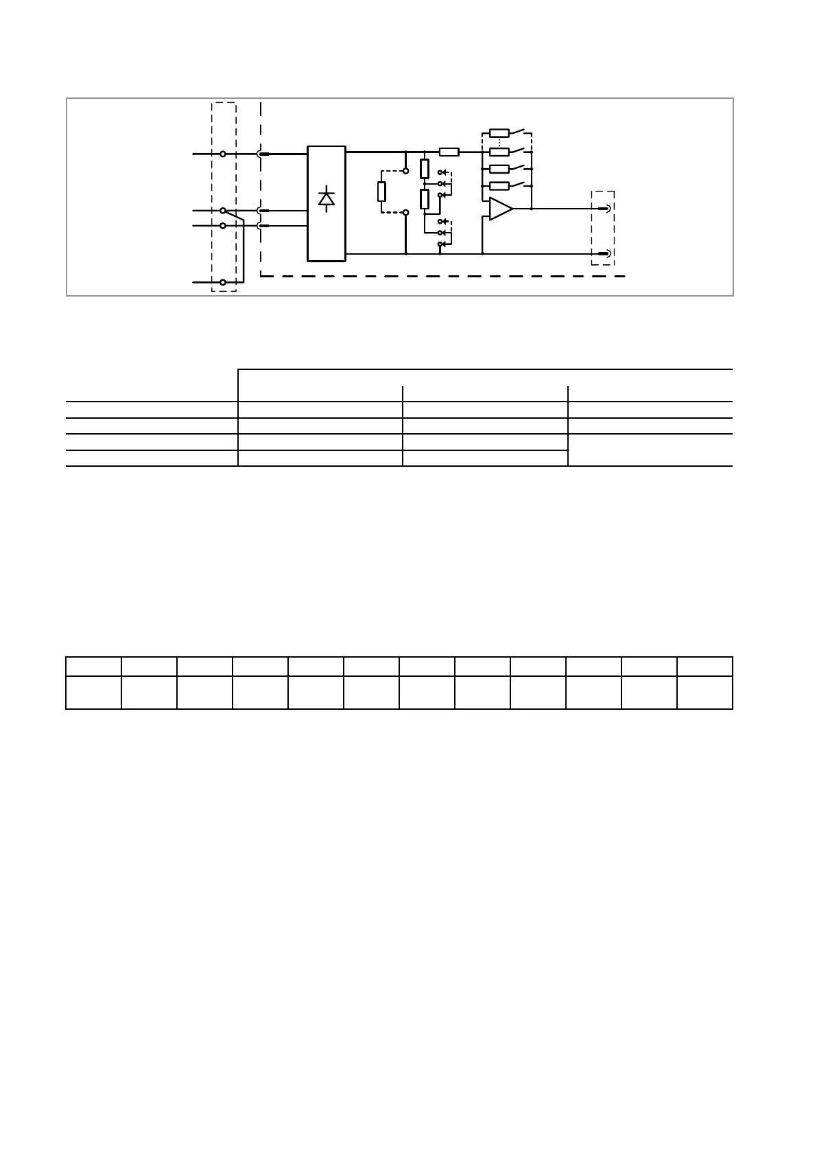
Figure A1.6.3.1: Detail of circuit
567
5
678
KPT31
TH-CT
External
burden R
XCT
0VI
RCT
J5
J4
Armature current
feedback
2R52R5
SW3,
SW4
N8
14 13XR
to R-TPD32
FIRXP-XX board
from CTs
J5A
J4A
IfthesecondarycurrentoftheCTsinstalledis<1A,the2.5Ohmor5Ohmburdenresistorsalreadyprovided
onthecardcanbeused;forsecondarycurrentsof>1Aand<5Atheburdenresistormustbeconnectedbetween
terminalsRCTand0VI,excludingtheinternalresistors.Intableform:
CT secondary current
< 0.5A > 0.5A, < 1A > 1A, < 5A
Jumper J4 J4A (OFF) J4 (ON) irrelevant
Jumper J5 J5 (ON) J5 (ON) J5A (OFF)
Ext. resistor RCT Not connected Not connected
See example of calculation
R resulting load (Rb) 5 Ohm 2,5 Ohm
note: Sometimes,especiallyinrevampingprojects,currenttransducerswitha5Asecondarycur-
rentmayalreadybeinstalledonthepowerbridges.Itisstillpossibletousejusttheinternal
resistors:simplyinserttwomore5A/1Aor5A/0.5Acurrenttransducers,althoughthiscould
affecttheultimateaccuracyofcurrentmeasurement.
- At100%ofthedrive’sratedcurrent(IdN),theaveragereactionvoltage,appliedbetweenpinsXR-13/
XR-14(0V)is 0.612 V.
- Dip-switchS3-1representsthemostsignicantbit(MSB)anddip-switchS4-8theleastsignicantbit
(LSB).Aclosedswitch(“ON”)meansbinaryvalue1,anopenswitch(“OFF”)means0.Ingraphform
SW3-1 SW3-2 SW3-3 SW3-4 SW4-1 SW4-2 SW4-3 SW4-4 SW4-5 SW4-6 SW4-7 SW4-8
bit 11
MSB
bit 10 bit 9 bit 8 bit 7 bit 6 bit 5 bit 4 bit 3 bit 2 bit 1 bit 0
LSB
- Themaximumgainoftheamplieris51.2(inactualfact–51.2)andtheminimumgainis0.0125005
withpossiblevaluesof212–1.
- Thebinaryconguration00....000(allS3andS4switchesopen),isnotallowed!
- Therelationbetweenampliergain(“Gain_required”)andbinarynumber(“Binary_switch_setting”)
isgivenby:
1 51,2
Binary_switch_setting = --------------------- x 51,2 = ---------------------
Gain_required Gain_required
Clearly,onlythewholenumberoftheresultoftheaboveequationisconvertedintoabinarynumber.
Thevariablesusedinthefollowingexamplesofcalculationare:
- Id
N=drivearmatureratedcurrentinA;
- CT=currenttransducerwithatransformationratioof:Iprim/Isec;
- Rb=burdenresistorinOhm;
- Vf@Id
N=reactionvoltageatarmatureratedcurrent:0.612V;
- Vb@Id
N=reactionvoltageontheburdenresistorattheratedarmaturecurrentinV.
 Loading...


