—————— TPD32-EV ——————
80
4.7 DIGITAL ENCODER INTERFACE DEII
4.7.1 Description
TheoptioncardDEIIhasbeenprojectedtoadapt,toseparategalvanicallyandtoconnectadigitalencoderto
theinputXE1oftheconvertersTPD32-EVregulationsboards.Asstandard,thisinputisarrangedforthecon-
nectionofananalogencoder.
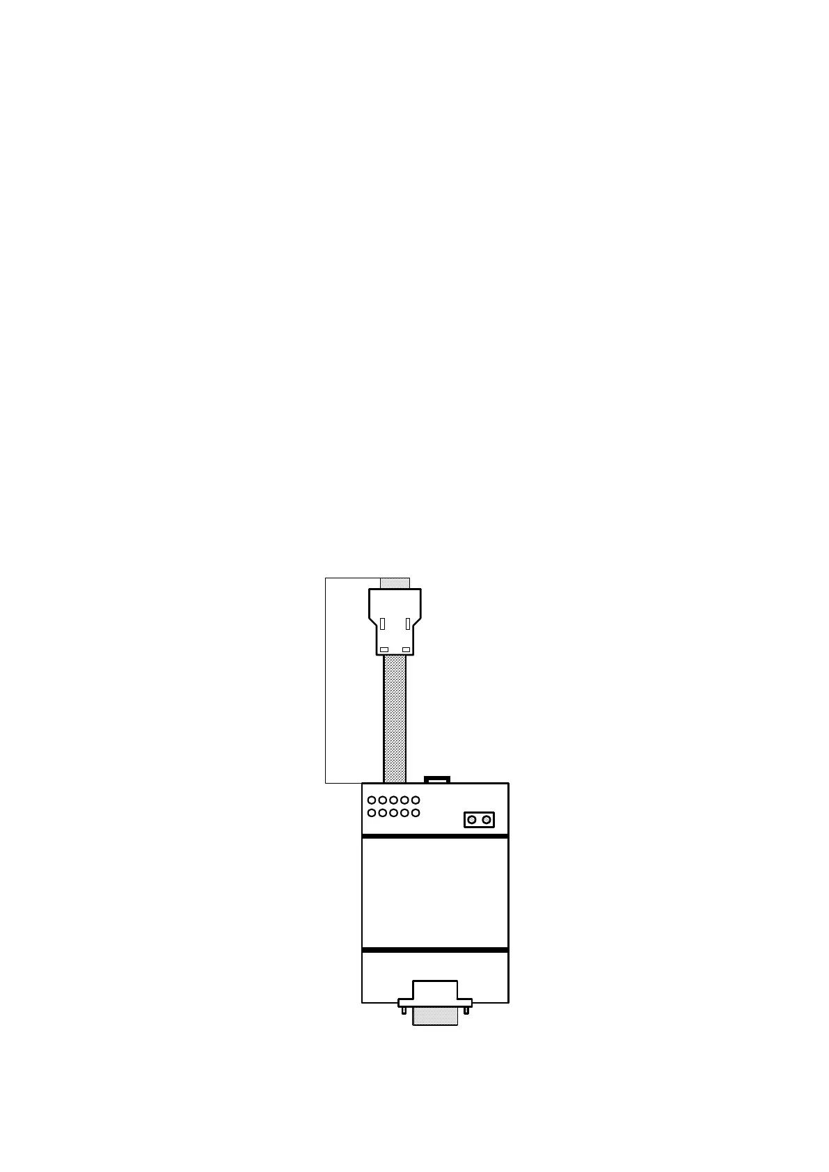
ThecardDEIIwillbexedexternallytothedrivebythemountingrailDINEN50022-35.Theinputfemale
connectorXS1mustbeconnectedtothedigitalencoderusinga9-polemaleconnector,throughashieldedcable,
Taskerc/186(6x2x0.22)withamaximallengthof150m.
MaleoutputconnectorXS2with1.5mshieldedcablemustbeconnectedtothe9-pinconnectorttedonthe
TPD32-EVcontrolcard.Theinputvoltagecanbe15V...24V(HTL)or5V(TTL),dependingonwhetherthe
encodertobeconnectedistypeHTLorTTL.Whenthevoltageconnectedtoterminals+Vencand0Vencis
switchedon,theHTLorTTLLEDwilllightup.IftheencoderhasHTLoutputs,switchS1-S2-S3mustbe
positionedonHTLside(defaultconguration);ontheoppositesideiftheencoderhasaTTLoutput.Ifswitch
S1-S2-S3ispositionedonTTLside,voltage+Vencisalsoconnectedtopin9ofXS1,inadditiontopin2.
S4jumperisusedtocutoutthechannelC(noimpulse)fromthetestofencoderloss.S4closed=canalCin-
cluded,S4open=canalCcutout.TheELLEDlightsuptosignaltheabsenceofatleastoneencodersignal.
Thefunctionthatcheckstheabsenceofencodersignalsworkscorrectlyonlywithencoderswithcomplementary
outputs.ItdoesNOTworkwithsingle-endedencoderdrivers.
ThejumperSHismountedonconditionofstandarddelivery;itmustbecutonlyincaseoftheshieldsideen-
coderisconnectedtothechassisofthemotor,toavoidtheformingagroundring.
ForconverteroperationwiththeDEIIcarditisnecessarytosetthejumperS5,S6ontheregulationboardin
positionA.
1
3
579
4268SH
XS1
+Venc
0Venc
Cable Length = 1.5m
DEII
XS2
Figure 4.7.1.1: DEII card
 Loading...


