25 Replacing Controller Components
Replacing Controller Components
Observe safety information!
The device must be disconnected from the power and compressed air
supply!
- Undo 8 screws on the front panel and carefully detach the front panel.
- Disconnect 2 cables leading from the front panel to the device.
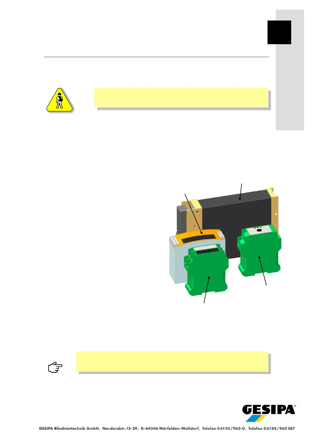
Control module
- The control module is installed in two holders
on the base of the rear panel of the enclo-
sure and is removed by carefully pulling up-
wards.
- he 28-pin central connector on the control
module is secured by a clip which is re-
leased to remove the module.
- Take particular care when reinstalling in re-
verse order to ensure that the retaining clip
is fully engaged on the central connector and
the control module is correctly plugged in to
both holders.
Switched-mode power supply unit and
electronics module
- The plug connections are carefully released
with a screwdriver.
- The switched-mode power supply unit and
the electronics module are plugged onto the
mounting rails (top hat rails) on the base of
the enclosure and can be released with a
screwdriver.
- When reinstalling, the module and connect-
ors are plugged in in reverse order.
Particular care must be taken to ensure that the connector locks in correct-
ly when reinstalling the plug connections!
Switched-mode
power supply unit
Electronics module
Displacement sensor
Electronics module
Vibration feed unit