29 Displacement sensor (WS1) teach-in
Displacement sensor (WS1) teach-in
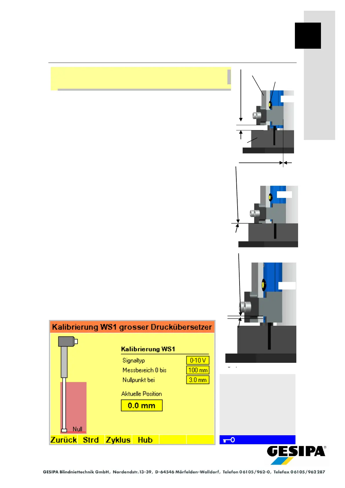
29.0 Defining measuring range at displacement sensor
- Align the bottom of the sensor holder unit with the top of the
baseplate with a gap of 5.0 mm (use shim if necessary) (see
Pos. 1).
- Keep the yellow button on the displacement sensor pressed
until the LED flashes. Release the yellow button; the zero
point is stored.
- With the LED still flashing, fit the sensor holder unit onto the
top of the baseplate (remove shim if necessary) (see Pos.
2).
- Press "Stroke" button F4 on the display (piston in pressure
booster moves up), press yellow button on the displacement
sensor again until the flashing LED switches to steady light. The
end position is now stored and the measuring range of the dis-
placement sensor set.
- Press the "Stroke" button F4 again on the display, the piston
in the pressure booster moves back into its initial position.
- To set the installation dimension, the sensor holder unit must
be moved upward until 0.00 mm is shown for the "Current
Position" on the display. Now secure the sensor holder in
this position (Pos. 3).
If the adjustment procedure is not completed, a timeout will take
place after 90 s and the measuring range last stored will be
active. Readjustment will be required and the teach-in pro-
cedure must be repeated.
Resetting to factory setting:
- Keep the yellow button on the displacement sensor pressed
for > 5 s until the LED lights continuously. This resets the
displacement sensor to the factory setting
(= max. possible measuring range).
Navigation:
AUTO
► MAN
► Menu
► GAV settings
► Large pressure booster
► Cal
Calibration menu
Displacement sensor WS1
Large pressure booster
During each step in the further procedure, the long side of the dis-
placement sensor must rest against the cylinder wall of the pres-
sure booster.
Pos.3 Installation dimension =
value
"Current position" 0.0 mm
Installation dimension
0 mm
Pos. 1 Zero position (ZP)
Teach-in dimension = 5.0
mm
Pos. 2 End point (EP)
Teach-in dimension = 0.0
mm