Functional Description
7 Functional Diagrams and Description
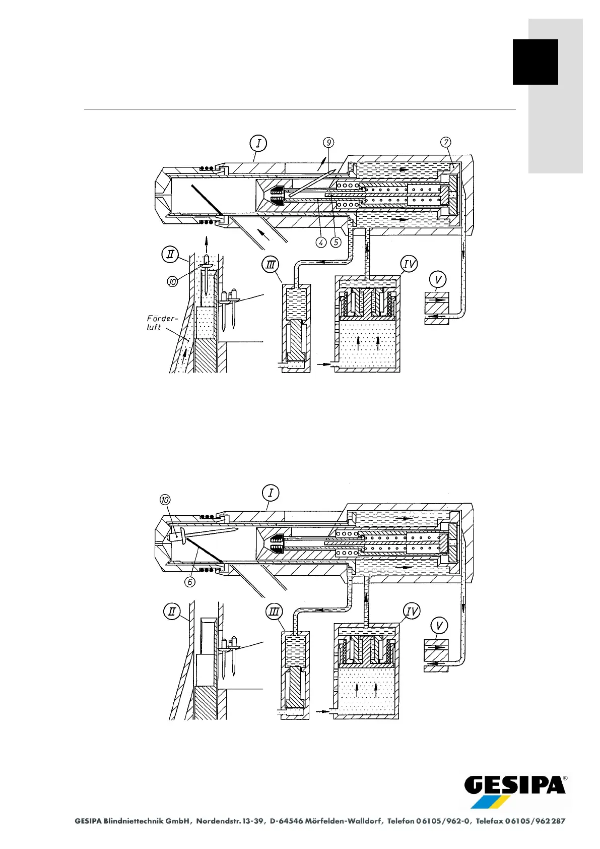
Functional diagram 3
The pressure booster (IV) continues applying pressure to the pull piston (7) so that it moves to
the rear end position. Valve (V) switches to vent off the reset air. The stop piston (5) and jaw
tube (4) are relieved and the jaws (3) release the blind rivet mandrel (9). The blind rivet feed air
is switched on by a control pulse at the pressure booster (IV), the blind rivet (10) in the separa-
tor (II) is loaded and the broken mandrel (9) is ejected.
Functional diagram 4
The lock spring (6) positions the blind rivet (10) in the gun head.