Functional Description
7 Functional Diagrams and Description
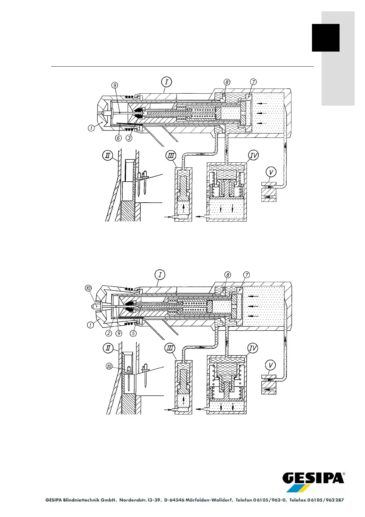
Functional diagram 5
The valve (V) releases the reset air and the pull piston (7) as well as the piston in the pressure
booster (IV) are reset to their initial position. At the same time, the pressure booster (III) applies
pressure to the pressure piston (8) to execute the release stroke for the spreader nosepiece (1).
The blind rivet mandrel (9) is taken up by the gripping mechanism and centred in the jaws (3).
Functional diagram 6
As the pull piston (7) moves back, the blind rivet mandrel (9) knocks against the stop piston (5)
so that the blind rivet (10) opens the spreader nosepiece (1) and assumes the processing posi-
tion. The pressure piston (8) executes the locking stroke for the spreader nosepiece (1) after the
pressure booster (III) relieves the pressure. Triggered by a switching pulse at the pressure
booster (IV) a further blind rivet (10) is set in the separator (II).