WIRING DIAGRAMS
FA-Plus/C or FA-Plus
SEC
PRI
~~
Main
+ +
--
Place this power supply
unit as close as possible
to the first distributor.
1,00mm²
2,50mm²
0,25mm²
0,25mm²
RG-59
RG-59
Terminal
SECTIONS CHART
50m.
Sections up to
150m.
A , A , A, D
in out
V , V , V , V
in+ out+ in out
+, , CV1, CV2
–
Remove the JP1 jumper
from all of the distributors
except the last.
A
A
_
_
+
+
D
D
Malla
Malla
V
in
V
in
V
out
V
out
CN4
CN4
A
_
+
D
Malla
V
in
V
out
CN4
A
_
+
D
Malla
V
in
V
out
CN4
E
E
D1
D1
D2
D2
+
+
D4L-PLUS
D4L-PLUS
JP1
JP1
S
S
Characteristics of the coaxial cable RG-59 B/U MIL C-17.
FA-Plus/C
SEC
PRI
230
Main
110 0
--
+ +
*
*
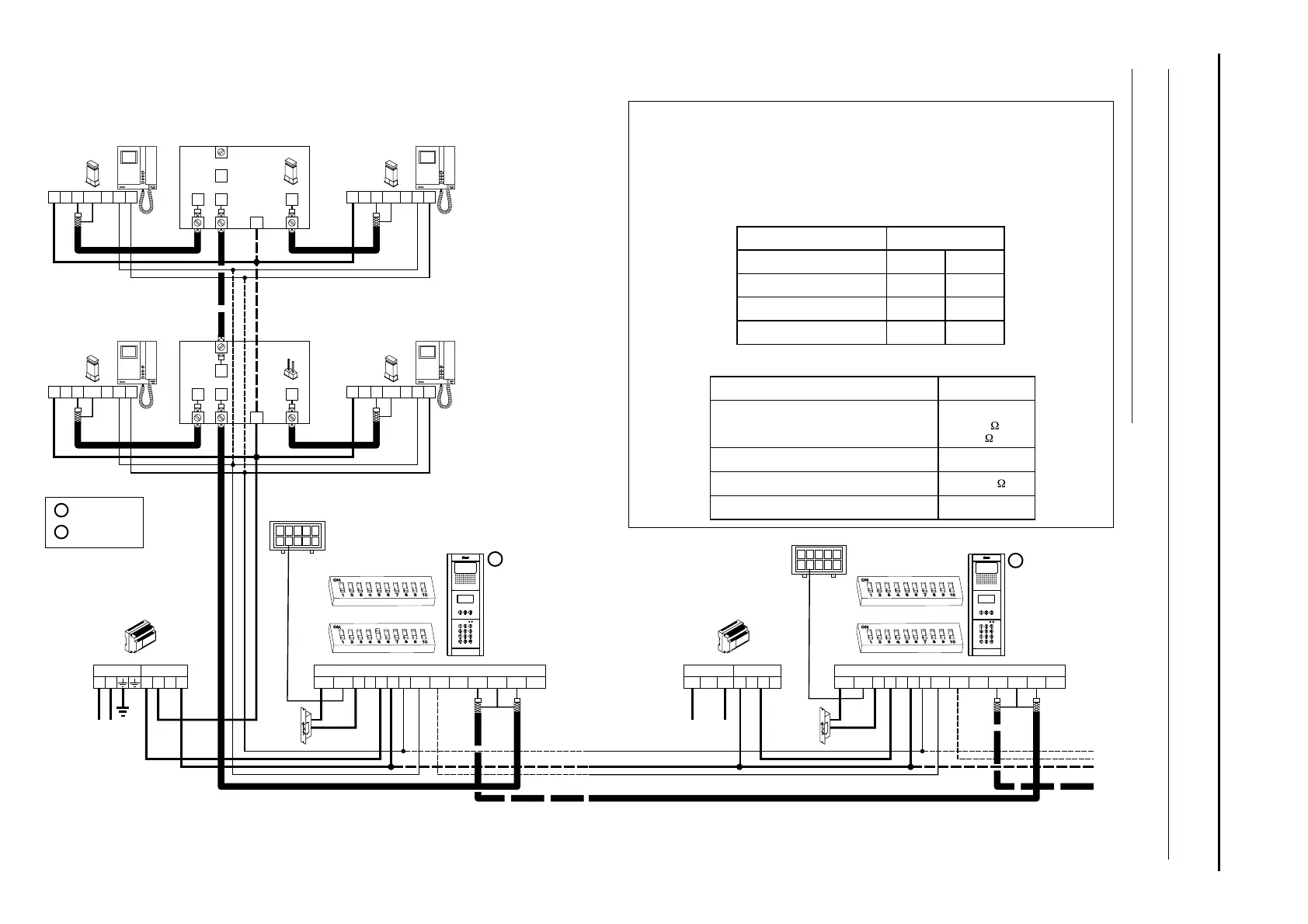
The wiring diagram shows the connection of a video door entry system with one or
more door panels to enter the building.
If the system has only one door panel, disregard the connection to the others.
If the system however has more than one door panel, connect the second panel as
shown in the diagram. If there are more than two door panels, connect the others
in the same way as the second.
Electrical resistance of the conductor at 20°C
Interior (live)
Exterior ( )shield
ELECTRICAL CHARACTERISTICS
Rated capacity
Characteristic impedance
VALUES
*
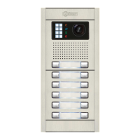
Access panel
Access panel
M =Master.
S =Slave.
Propagation speed
DC
lock release
.
DC
lock release
.
75 3
+
-
<67pf/m
<158 /Km
<10 /Km
_
_
_
_
>66,6 %
Video door entry system with coaxial cable:
P
D
Malla
Vin-
Ain
Aout
Vin+
Vout-
Vout+
CN1
+
-
+
CV1CV2
-
10
1
9
2
8
3
7
4
6
5
CN3
S
D
Malla
Vin-
Ain
Aout
Vin+
Vout-
Vout+
CN1
+
-
+
CV1CV2
-
10
1
9
2
8
3
7
4
6
5
CN3
143
SW2
SW1
SW1
SW2
AUDIO AND VIDEO DOOR ENTRY SYSTEM - CODED PANEL WITH DISPLAY

 Loading...