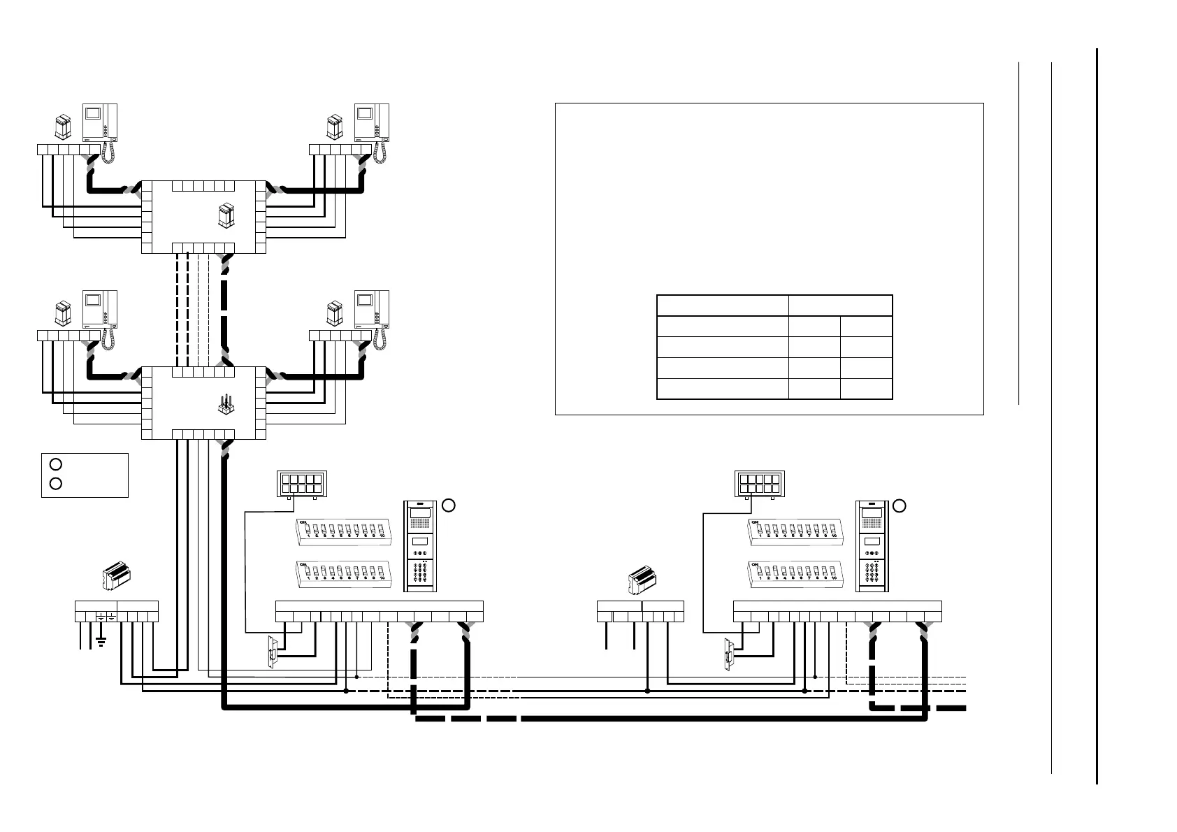
WIRING DIAGRAMS
Video door entry system without coaxial cable:
FA-Plus/C or FA-Plus
SEC
PRI
~~
Main
+ +
--
*Place this power supply
unit as close as possible
to the first distributor.
1,00mm²
2,50mm²
0,25mm²
0,25mm²
CAT-5
CAT-5
Terminal
SECTIONS CHART
50m.
Sections up to
150m.
A , A , A, D
in out
V , V , V , M
in+,- out+,- p,d p,d
+, , CV1, CV2
–
*
Remove the JP1 jumper
from all of the distributors
except the last.
JP1
A
A
D
D
CT
+
+
V
pi
V
d1
M
pi
M
d1
_
_
A
D
CT
+
V
d6
M
d6
_
A D
+
V
po
M
po
_
D6L-Plus/2H
V
p
M
p
A D
_
+
EL562
JP1
V
p
M
p
A D
_
+
EL562
JP1
JP1
A
A
D
D
CT
+
+
V
pi
V
d1
M
pi
M
d1
_
_
A
D
CT
+
V
d6
M
d6
_
A D
+
V
po
M
po
_
D6L-Plus/2H
V
p
M
p
A D
_
+
EL562
JP1
V
p
M
p
A D
_
+
EL562
JP1
The wiring diagram shows the connection of a video door entry system with one or
more door panels to enter the building.
If the system has only one door panel, disregard the connection to the others.
If the system however has more than one door panel, connect the second panel
as shown in the diagram. If there are more than two door panels, connect the
others in the same way as the second.
I
MPORTANT: This type of installation requires DIP-3 of the SW1 DIP switch to be
set to ON (p. 1 ) and the monitors to use the EL562 module03
see "TTekna Plus SE" manual)( .
M =Master.
S =Slave.
FA-Plus/C
Main
SEC
PRI
230
110 0
--
+ +
Access panel
Access panel
S
P
D
Malla
Vin-
AinAout
Vin+
Vout-Vout+
CN1
+
-
+
CV1CV2
-
10
1
9
2
8
3
7
4
6
5
CN3
DC
lock release
.
DC
lock release
.
D
Malla
Vin-
AinAout
Vin+
Vout-Vout+
CN1
+
-
+
CV1CV2
-
10
1
9
2
8
3
7
4
6
5
CN3
SW1
144
SW1
SW2
SW2
AUDIO AND VIDEO DOOR ENTRY SYSTEM - CODED PANEL WITH DISPLAY

 Loading...