7 System Utilities and Tools
68 User Guide
7.4 Back Side Alignment
The following section informs about the back side alignment (BSA) preparation and
exposure procedure.
7.4.1 OVERVIEW OF BSA MARKER ZONES
The MLA150 comes with a multi-purpose chuck ready to expose both large and small
substrates.
For BSA, the chuck provides four designated openings. Markers located in these areas
are detected by the BSA camera system and used for alignment.
Each opening is 10 mm wide and 46 mm or 76 mm long. The first edge is located
12 mm or 14.5 mm from the center of the chuck. The BSA markers can be positioned
anywhere in this area.
For easy handling and good resolution, Heidelberg Instruments recommends to position
the markers on the main axis and about 10 mm from the edge of the wafer. Proposal for
marker: cross of size 300 µm x 300 µm, Linewidth 20 µm.
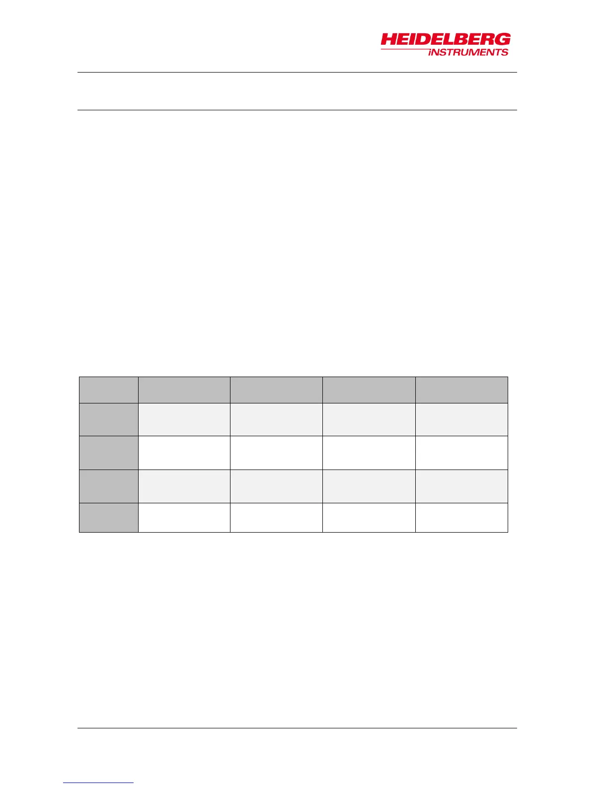
Proposal for marker positions (x/y):