3 System Description
22 User Guide
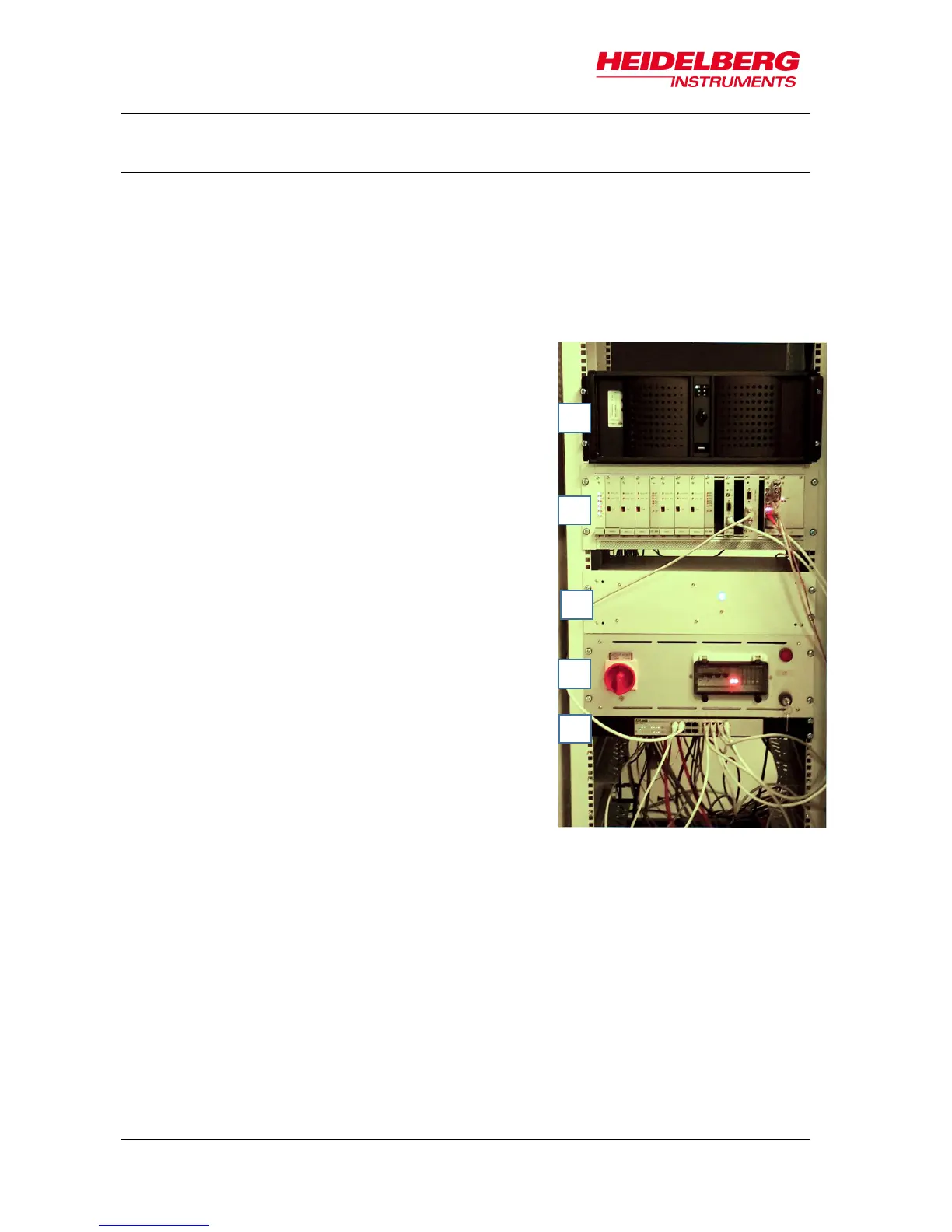
3.2 Electronics Rack
The electronics rack consists of several units. These units drive and control the system
and provide communication with the operator of the system. The following electronic
units are located inside the electronics rack:
1 USER PC WITH CONVERSION
The User PC is a communication interface
between user and system by means of the
graphical user interface (GUI). The User PC
runs Linux on a virtual machine which runs the
conversion software. This software is
necessary for design conversion. Design files
in Gerber, DXF, CIF or GDSII have to be
converted into a machine file format, the LIC
format. LIC stands for Laser Internal Code.
Only this special file format can be read by the
MLA system.
2 STC-RACK
The STC-Rack is a system control unit
consisting of several elements such as the
stepper motor driver, the autofocus electronics
or the laser shutter control.
3 STAGE CONTROLLER
The Stage Controller drives the stage, reads
the interferometer data, triggers the laser and
tells the DMD (digital micromirror device) when
to switch to the next frame. It is the system that
coordinates the exposure procedure.
4 POWER SUPPLY AND EMERGENCY STOP
MODULE
This unit responsible for power distribution.
5 INTEGRATED NETWORK HUB
The Integrated Network Hub connects the
multiple devices and make them work together
on a single network.