7 System Utilities and Tools
70 User Guide
7.4.2 BSA EXPOSURE PREPARATION
Back side alignment is mainly done in two steps. Follow the instructions on the BSA
exposure steps
Step 1:
Expose the pattern on side A with the BSA markers.
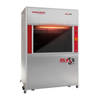
Position your markers inside the BSA marker zones. The
recommended cross linewidth is 20 µm.
Prepare a strategy to find the markers during alignment:
a larger cross is easier to find
add small marks for orientation
When using the mirror function during design import,
remember to click update to all layers.
Step 2:
After processing of side A, position wafer on chuck with side B on top
Remove the inlets of the required BSA holes in the chuck.
Define your default marker positions in the MLA150 menu. Select Backside
Camera for this measurement.
Execute alignment exposure as usual.
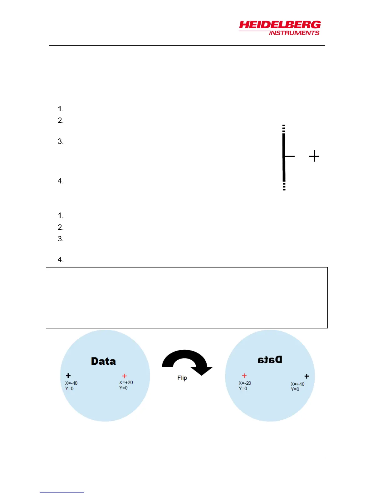
The coordinate system of the MLA does not change during back side alignment.
Reference is always the top of the wafer. This means:
The x-coordinate changes prefix on the back side of the wafer. A marker that was
written to position +x is now at position –x. When you use the control panel for
movements, the camera picture will move to the left when you click the "to the right"
button.