HEIDENHAIN MANUALplus 620 339
4.26 Milling Cycles
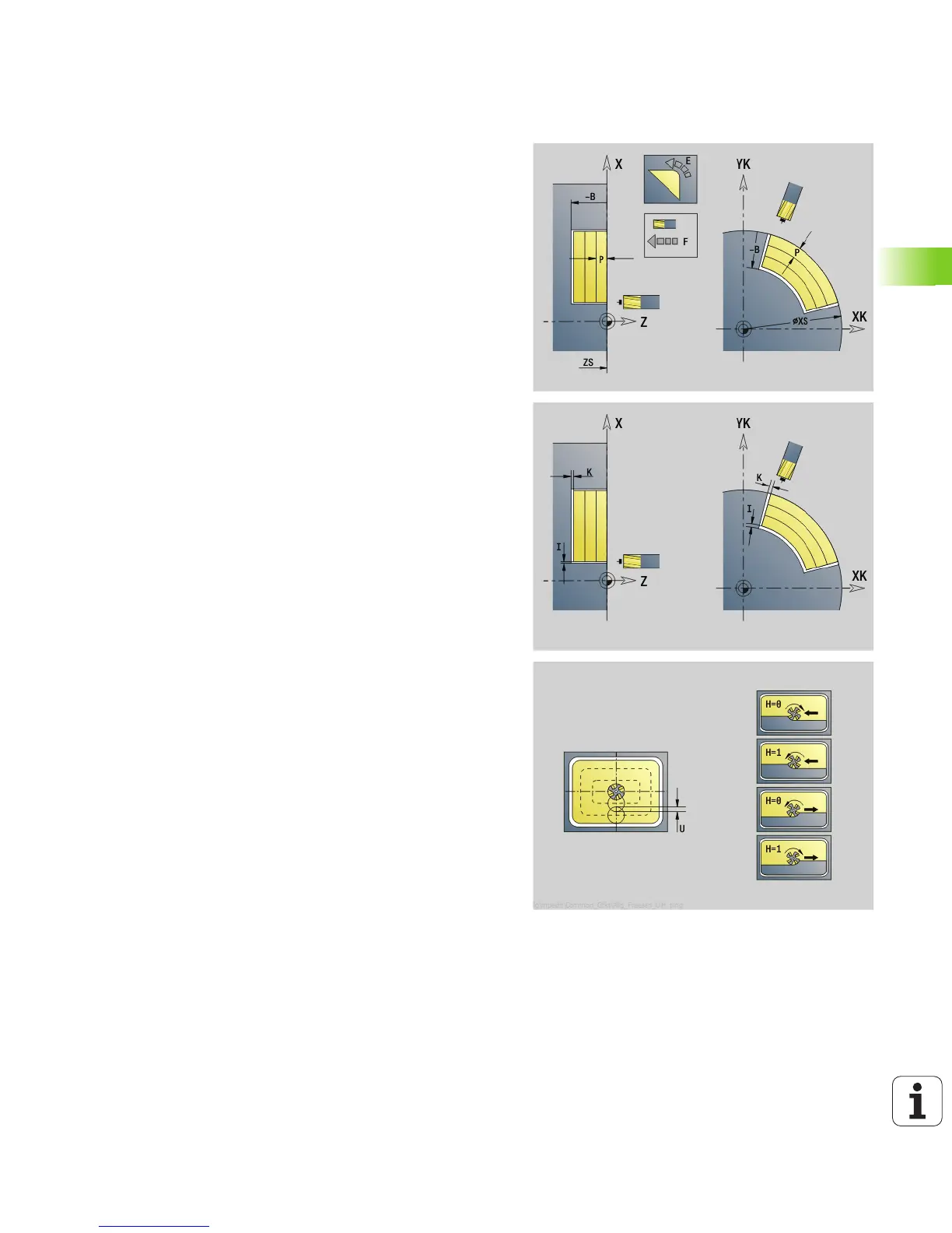
G845—Milling
You can change the cutting direction with the cutting direction H,
the machining direction Q and the direction of tool rotation (see
following table). Program only the parameters given in the following
table.
See also:
G845—Fundamentals: Page 337
G845—Calculating hole positions: Page 338
Parameters—Milling
ID Milling contour—name of the contour to be milled
NS Contour start block no.
Figures: Block number of the figure
Free closed contour: A contour element (not starting point)
B Milling depth (default: depth from the contour description)
P (Maximum) approach (default: milling in one infeed)
XS Milling top edge—lateral surface (replaces the reference
plane from the contour definition)
ZS Milling top edge—face (replaces the reference plane from the
contour definition)
I Oversize in X direction (radius)
K Oversize in Z direction
U (Minimum) overlap factor. Defines the overlap of milling paths
(default: 0.5).
Overlap = U*milling diameter
V Overrun factor (no effect with C-axis machining)
H Cutting direction (default: 0)
0: Up-cut milling
1: Climb milling
F Approach feed for infeed (default: active feed rate)
E Reduced feed rate for circular elements (default: current feed
rate)
RB Return plane (default: back to starting position)
Front or rear face: Return position in Z direction
Lateral surface: Return position in X direction (diameter)
Q Machining direction (default: 0)
0: From the inside out (from the inside towards the outside)
1: From the outside in (from the outside towards the inside)

 Loading...


