HIMax System 9 Lifecycle
HI 801 001 E Rev. 4.01 Page 103 of 122
; A non-redundant connection is established
3. Plug a RJ-45 connector of a second patch cable in to the UP socket located on the
connector board of the right system bus module within the first base plate.
4. Plug the second RJ-45 connector of the same patch cable in to the DOWN socket
located on the connector board of the right system bus module within the second base
plate.
The two base plates are redundantly connected.
i
Patch cables colored or marked in a different way help avoiding mixing up cables, e.g., red
cables for system bus A, green cables for system bus B
9.1.5 Mounting a Connector Board
Tools and utilities
Screwdriver, slotted 0.8 x 4.0 mm
Matching connector board
To install the connector board
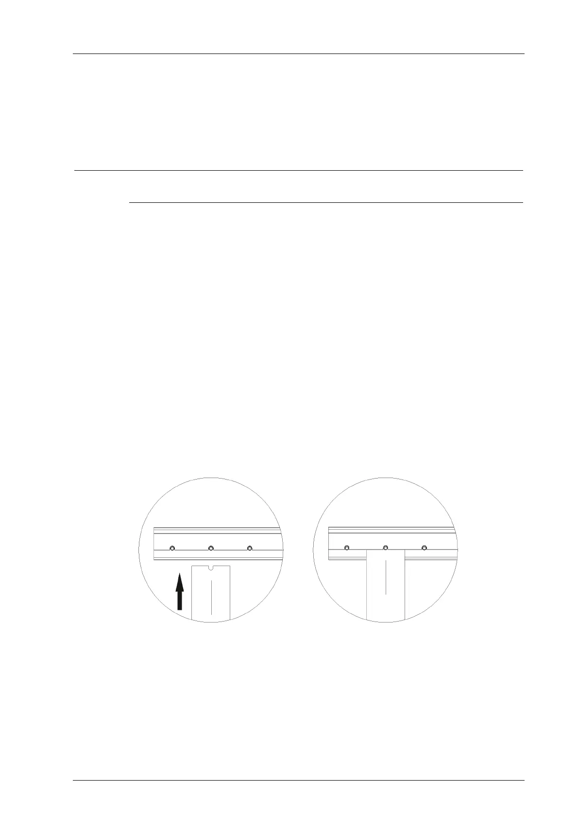
1. Insert the connector board into the guiding rail with the groove facing upwards (see
following figure). Fit the groove into the guiding rail pin.
2. Place the connector board on the cable shield rail.
3. Secure the two captive screws to the base plate. First screw in the lower than the upper
screw.
To remove the connector board
1. Release the captive screws from the base plate.
2. Lift the lower section of the connector board from the cable shield rail.
3. Remove the connector board from the guiding rail.
Figure 24: Inserting the Connector Board