3 Product Description HIMax System
HI 801 001 E Rev. 4.01 Page 28 of 122
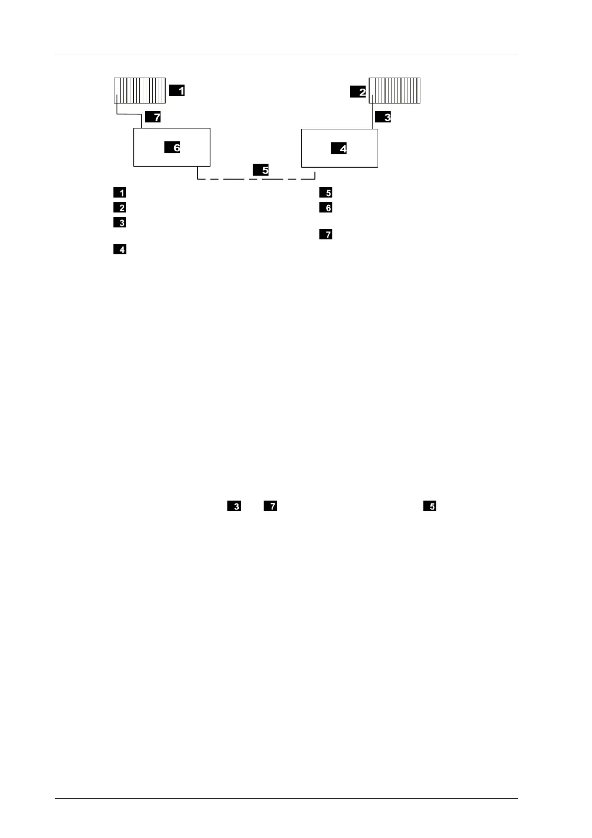
Rack A, connected to switch X
Rack B, connected to switch Y
Copper cable between rack B and
switch Y
Switch Y: Hirschmann SPIDER II Giga
5T/2S EEC Rail Switch
Fiber Optic Cable
Switch X: Hirschmann SPIDER II Giga
5T/2S EEC Rail Switch
Copper Cable Between Rack A and
Switch X
Figure 7: Connection of Two Base Plates through a Fiber Optic Cable
For connecting a fiber optic cable with two approved Hirschmann SPIDER II Giga switches,
the latency between the connector on system bus module in rack A and the connector on
system bus module in rack B must be calculated in accordance with the following formula:
t
Latency
= t
Cu1
+ t
Message
+ t
Switch X
+ t
Fibre optic cable
+ t
Message
+ t
Switch Y
+ t
Cu2
+ t
Message
t
Latency
Connection latency
t
Cu1
Copper cable latency between rack A
and switch X
See below
t
Switch X
Switch X latency 5 µs
t
Fiber optic cable
Fiber optic cable latency See below
t
Switch Y
Switch Y latency 5 µs
t
Cu2
Copper cable latency between rack B
and switch Y
See below
t
Message
Runtime for 1 GBit/s message, consid-
ered 1 time for each route
6.592 µs
The copper cable latency
and and the fiber optic cable latency must be
calculated as follows:
t = Damping*l/c
t
Copper cable or fiber optic cable la-
tency
t
Cu1
or t
Cu2
or t
Fiber optic cable
l Length of copper or fiber optic cable l
Cu1
or l
Cu2
or l
Fiber optic cable
c Light velocity approx. 300 000 km/s
Damping Copper or fiber optic cable damping 2 (assumed value for both)
Observe the following points when mounting the system bus:
The maximum latency between processor and communication modules must be
calculated in accordance with
Table 8 observing the distance to the base plates with
processor modules.
Only insert communication modules in base plates, for which such a latency can be
ensured!
The maximum latency between the two racks with processor modules or with
responsible system bus modules may be increased by 10 µs with respect to a standard
wiring, i.e., using a direct connection with 100 m copper cable at most.