HIMax System 7 Diagnosis
HI 801 001 E Rev. 4.01 Page 89 of 122
7.2 Diagnostic History
Each HIMax module maintains a diagnostic history about the occurred faults or other
events. The events in the history are stored in chronological order. The history is organized
as a ring buffer.
The diagnostic history is composed of short term diagnosis and long term diagnosis.
Short term diagnosis
If the maximum number of entries has been reached, each new entry deletes the oldest
entry.
Long term diagnosis
The long term diagnosis essentially stores actions and configuration changes performed
by the user.
If the maximum number of entries has been reached, each new entry deletes the oldest
entry if this is older than three days.
The new entry is rejected if the existing entries are not older than three days. The
rejection is marked by a special entry.
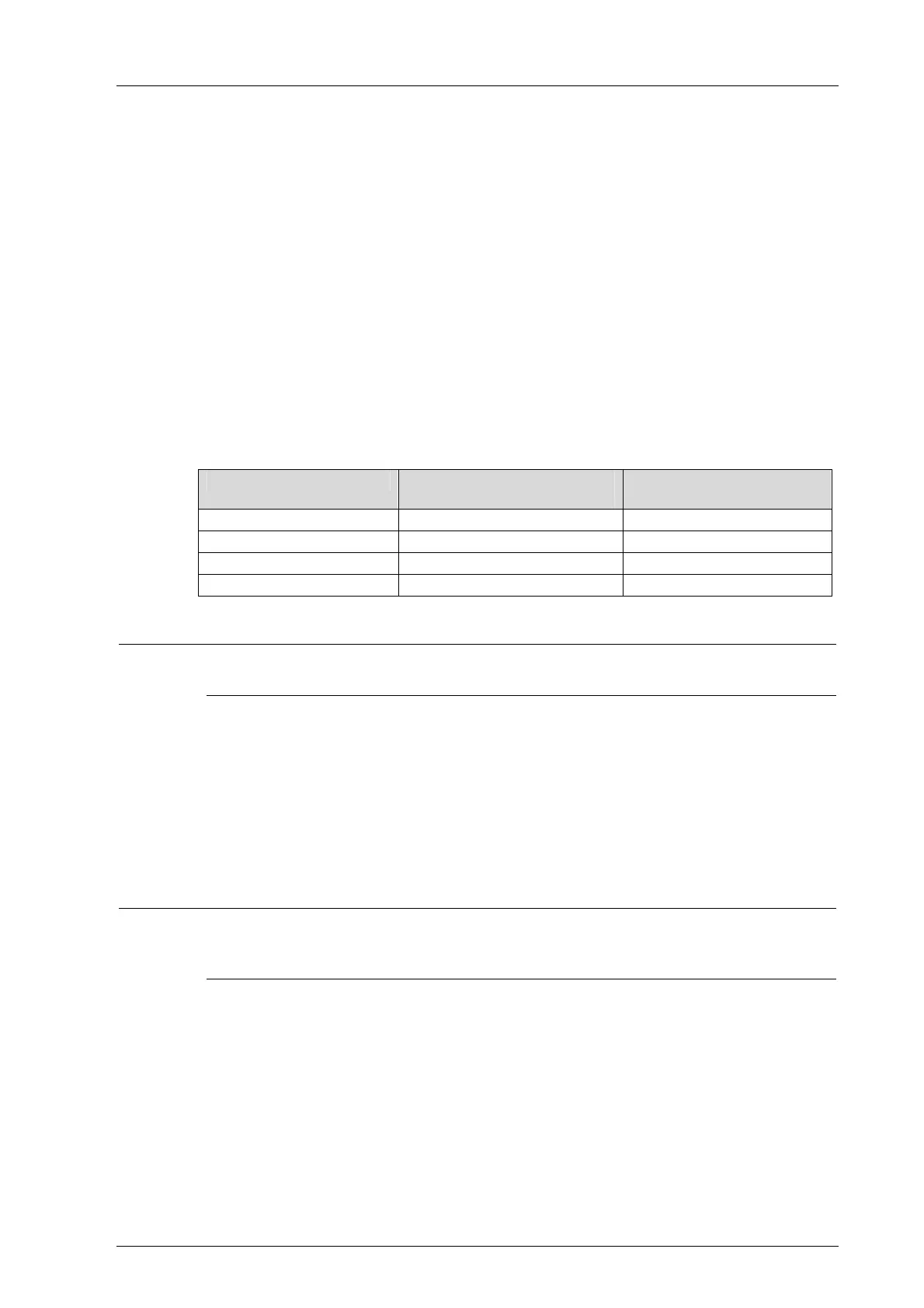
The number of events that can be stored depends on the type of module.
Module Type
Max. number of events
long term diagnosis
Max. number of events
short term diagnosis
X-CPU 01 2500 1500
X-COM 01 300 700
I/O modules 400 500
X-SB 01 400 500
Table 41: Maximum Number of Entries Stored in the Diagnostic History per Module Type
i
The diagnostic entries can be lost if a power outage occurs just before they could be saved
into non-volatile memory.
SILworX can be used to read the histories of the individual modules and represent them so
that the information required to analyze a problem is available. Example:
Mixing the histories from various sources
Filtering them according to the time period
Printing out the edited history
Saving the edited history
For additional functions, see the SILworX online help.
i
If a module is plugged in to a base plate, it generates diagnostic messages during its
initialization phase indicating faults such as incorrect voltage values.
These messages only indicate a module fault if they occur after the system starts operation.
7.3 Online Diagnosis
The Online View in the SILworX Hardware Editor is used to diagnose failures in the HIMax
modules. Failed modules are signalized by a color change:
Red indicates severe failures, e.g., that the module is not inserted.
Yellow indicates less severe failures, e.g., that the temperature threshold has been
exceeded.
Point to a module to display a tooltip providing the following state information about the
module: