HIMax System 7 Diagnosis
HI 801 001 E Rev. 4.01 Page 83 of 122
7 Diagnosis
The diagnostic LEDs are used to give a first quick overview of the system state. The
diagnostic history in SILworX provides detailed information.
7.1 Light Emitting Diodes
Light emitting diodes (LEDs) on the front plate indicate the module state. All LEDs should
be considered together. The state of one single LED is not sufficient to assess the module
state.
The LEDs on the modules are divided into the following groups:
Module status indicators
Redundancy indicators
Rack connection indicators
System bus indicators
Slot indicators
Maintenance indicators
Fault indicators
I/O indicators
Fieldbus indicators
Ethernet indicators
Communication indicators
When the voltage is connected, the module performs a test of the LEDs.
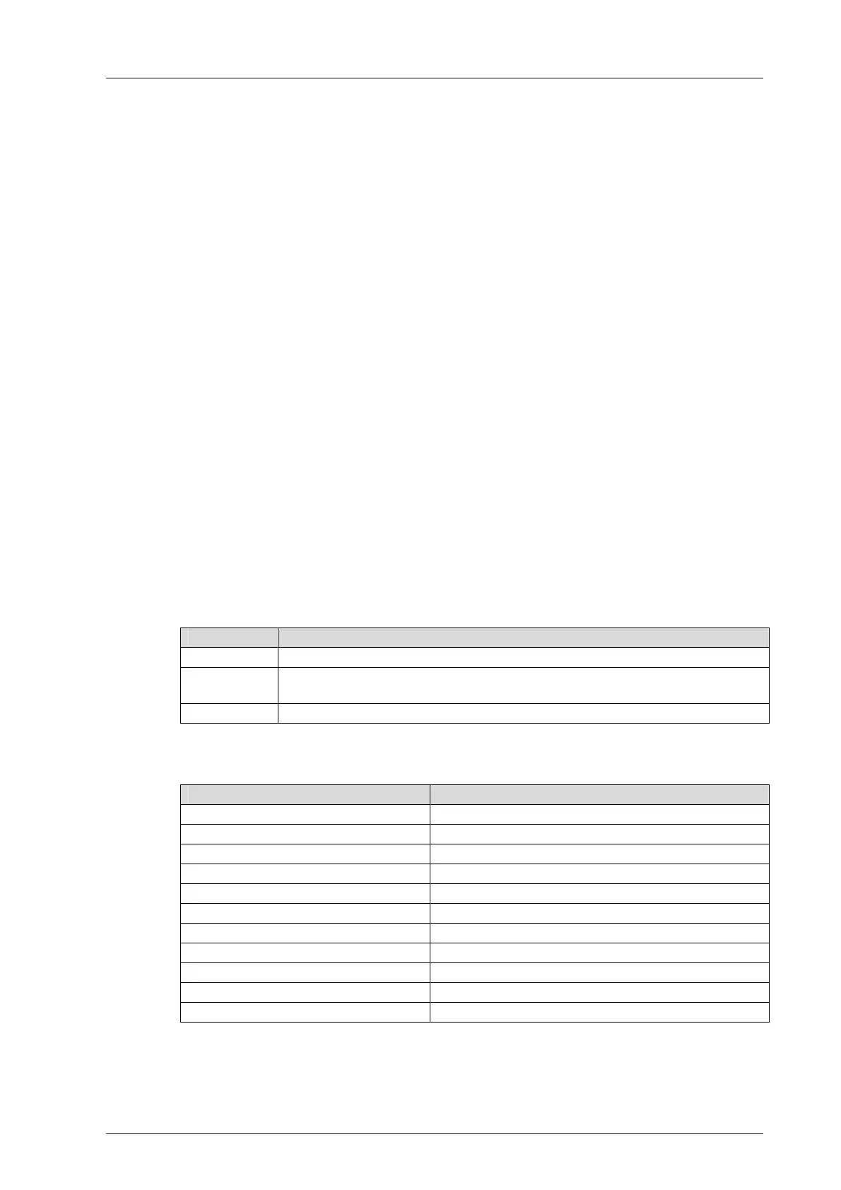
7.1.1 Definition of Blinking Frequencies
Blinking frequencies of the LEDs:
Designation Blinking frequencies
Blinking1 Long (approx. 600 ms) on, long (approx. 600 ms) off
Blinking2
Short (approx. 300 ms) on, short (approx. 300 ms) off, long (approx.
600 ms) on, long (approx. 600 ms) off
Blinking-x Ethernet communication flashing in sync with data transfer
Table 28: Blinking Frequencies
Assignment of the LED groups to the types of modules:
Groups Module types
Module Status Indicators All
Redundancy Indicators Processor module, system bus module
System Bus Indicators All, except for system bus module
Rack Connection Indicators System bus module
Slot Indicators System bus module
Maintenance Indicators Processor Module
Fault Indicators Processor module
I/O Indicators I/O modules
Fieldbus Indicators Communication module
Ethernet Indicators Processor module, communication module
Ethernet Indicators X-SB Module System bus module
Table 29: Assignment of the LED Groups to the Types of Modules