HIMax System 7 Diagnosis
HI 801 001 E Rev. 4.01 Page 87 of 122
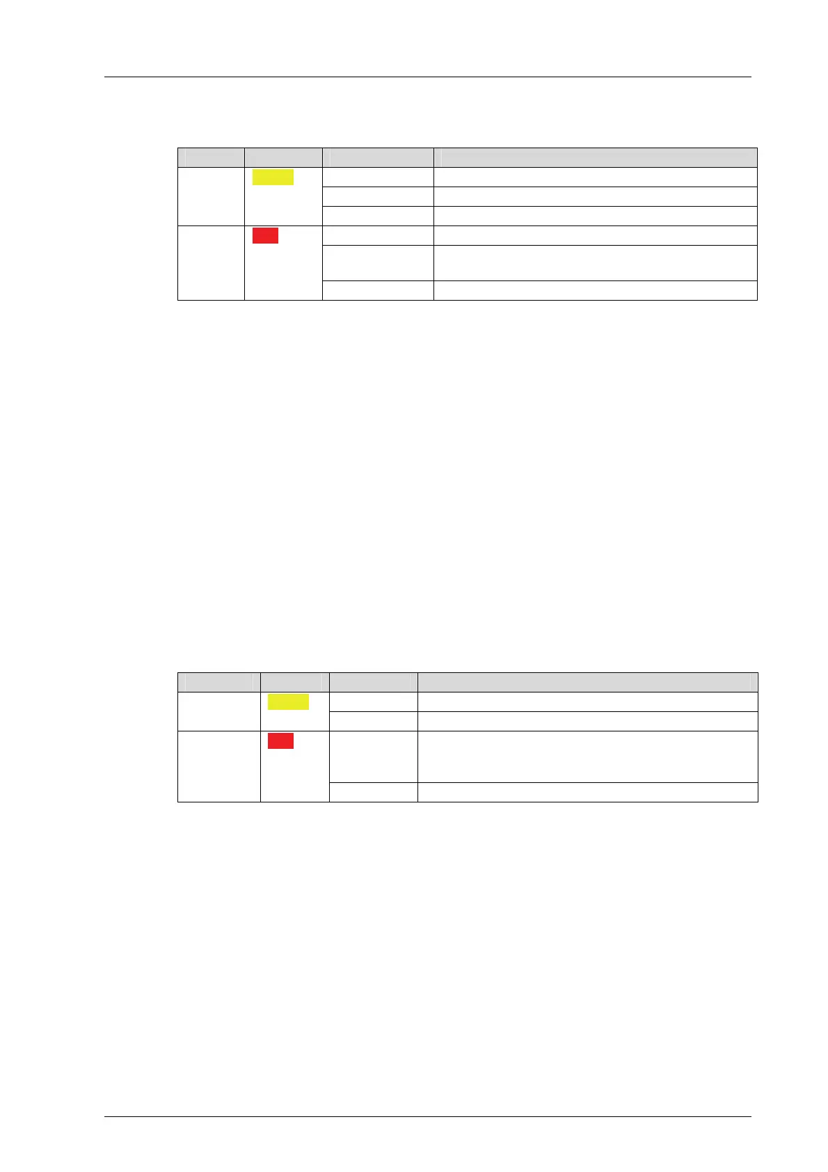
7.1.9 I/O Indicators
The LEDs of the I/O indicators are labeled Channel and Field.
LED Color Status Description
On The related channel is active (energized).
Blinking2 The related channel is faulty.
Channel
1 - n
Yellow
Off The related channel is inactive (de-energized).
On LED test while booting
Blinking1
Field faults in at least one channel (line break,
line short-circuit, over-current, etc.
Field Red
Off No field faults
Table 37: I/O Indicators LEDs
The number of channels and thus the number of Channel LEDs depends on the type of
input or output module.
With modules that (internally) operate in analog, the signal value of the Channel LEDs is
based on thresholds set during the planning phase:
The Channel LED is lit if the switching point set for HIGH (SP HIGH) has been
exceeded.
The Channel LED is no longer lit if the switching point set for LOW (SP LOW) has been
under-run.
The Channel LED state remains unchanged as long as one of the conditions previously
mentioned modifies it.
Depending on the module, the Field LED also indicates overvoltage, low voltage or
overcurrent of transmitter supply.
For more information on the I/O indicators for a specific module, refer to the corresponding
module manual.
7.1.10 Fieldbus Indicators
The fieldbus LEDs are labeled Fieldbus.
LED Color Status Description
On Fieldbus operating 1, 2 Yellow
Off No activity, fieldbus not operating
Blinking1
Fieldbus fault of the bus (e.g., the slave is not pre-
sent or faulty response), depending on the fieldbus
protocol (minimum blinking duration 5 s).
Fault Red
Off No fieldbus faults
Table 38: Fieldbus Indicators