9 Lifecycle HIMax System
HI 801 001 E Rev. 4.01 Page 94 of 122
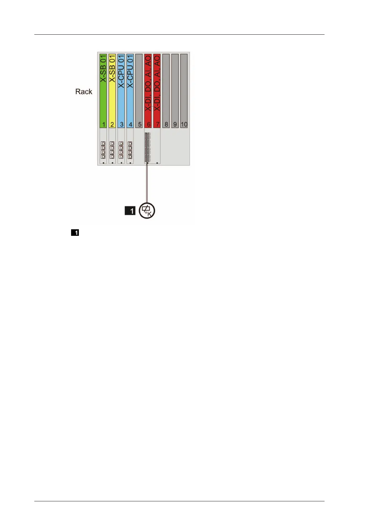
Sensor or Actuator
Figure 17: Wiring 2 - Redundant Connector Board with Screw Terminals
With wiring 2, connector boards of type 02, e.g., X-CB 008 02, are required in the base
plate.
Wiring 3
Connect the sensors or actuators to a single connector board with cable plug via field
termination assembly.
Connect the individual sensors or actuators to a field termination assembly on a per
channel basis.
Connect two or more redundant sensors or actuators to two or more redundant field
termination assembly on a per channel basis. Connect the field termination assembly to
a single connector board via field termination assembly. The number of redundant sen-
sors or actuators must be identical with the number of redundant modules (e.g., two
sensors/two modules).