9 Lifecycle HIMax System
HI 801 001 E Rev. 4.01 Page 98 of 122
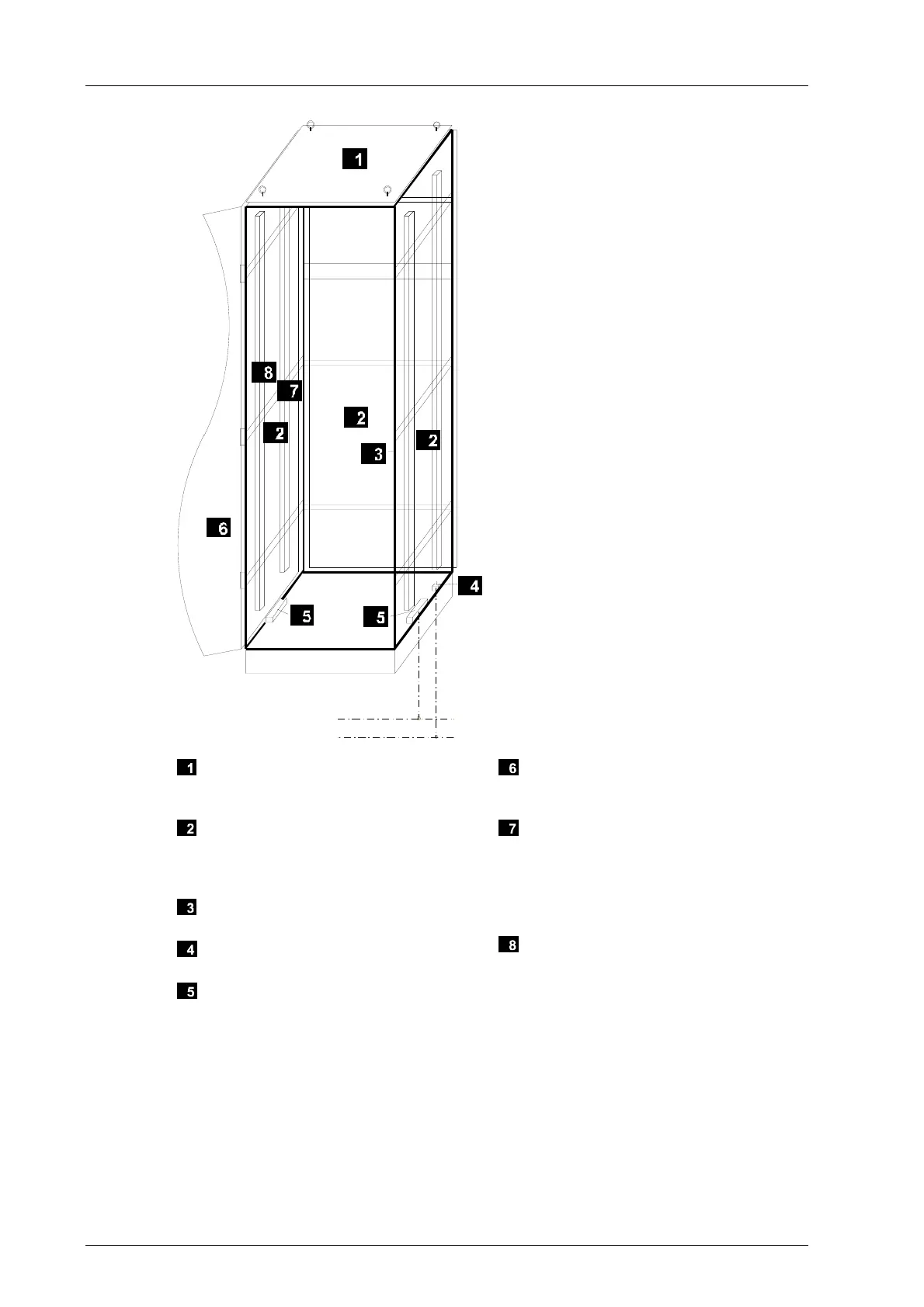
PA
PE
Shielding on the roof sheet connected
to the cabinet frame with standard fas-
teners
Shielding and earthing on the side pan-
els, backplane, floor panels and base
plate connected to the cabinet frame
with standard fasteners
The cabinet frame serves as the refer-
ence ground for the cabinet
Central grounding point for earthing the
cabinet frame (M8 bolts)
M 2500 busbars isolated from the cabi-
net ground and mounted on the cabinet
frame. These serve as the intake for
the potential bounding from the external
supply and the I/O cables from the field
Shielding and earthing of moveable
cabinet parts connected to the cabinet
frame with earthing straps
Standard fasteners used to earth me-
chanic parts such as the chassis. The
parts are connected to one another and
to the cabinet frame. 25 mm
2
earthing
straps are used to earth the mounting
plate
Potential bounding via mounting rails or
cable shield rails. Standard case: po-
tential bounding via protective earth
(PE). The rails must be electrically con-
nected to the chassis or to the mount-
ing plate.
Figure 20: Earthing Connections in the Control Cabinet
Use a 25 mm earthing strap when installing devices with a supply ≥ 60 VDC or ≥ 42 VAC.