HIMax System 7 Diagnosis
HI 801 001 E Rev. 4.01 Page 85 of 122
7.1.4 System Bus Indicators
The system bus LEDs are labeled Sys Bus.
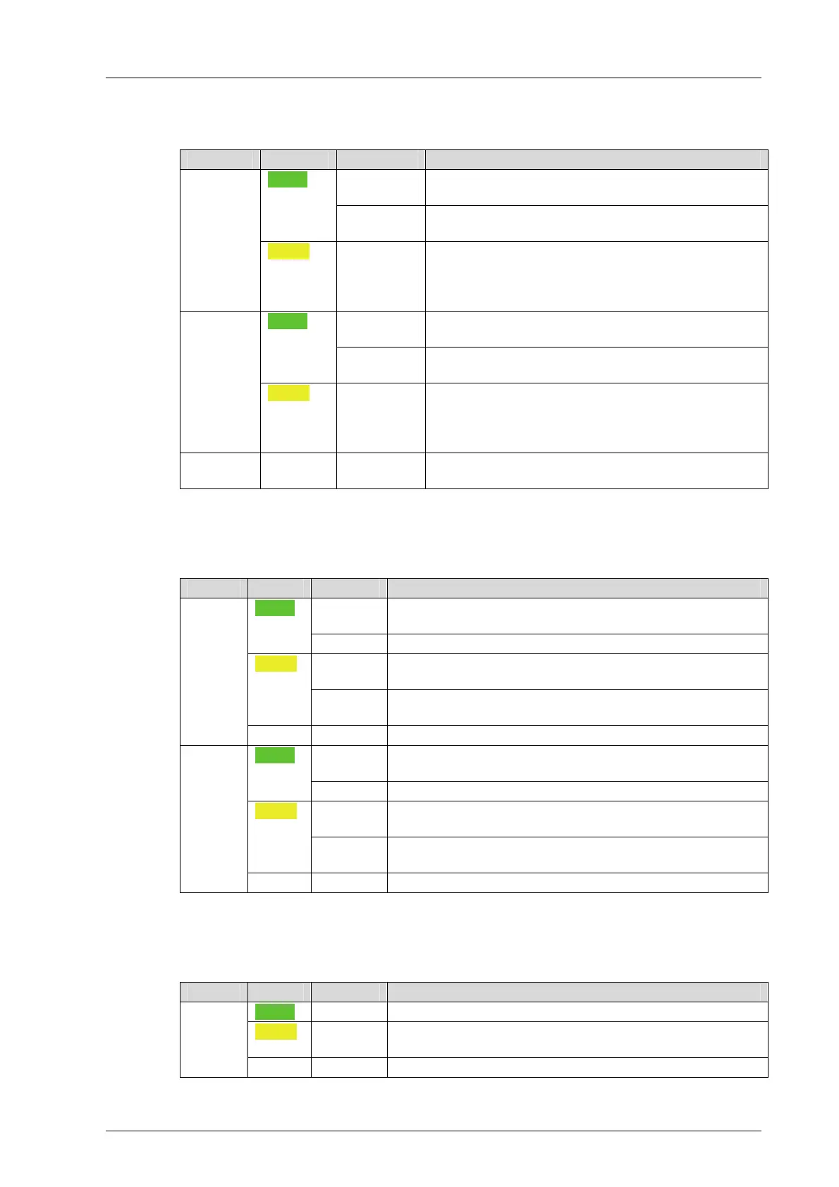
LED Color Status Description
On
Physical and logical connection to the system bus
module in slot 1.
Green
Blinking1
No physical connection to the system bus module in
slot 1.
A
Yellow Blinking1
The physical connection to the system bus module
in slot 1 has been established.
No connection to a (redundant) processor module
running in system operation.
On
Physical and logical connection to the system bus
module in slot 2.
Green
Blinking1
No physical connection to the system bus module in
slot 2.
B
Yellow Blinking1
The physical connection to the system bus module
in slot 2 has been established.
No connection to a (redundant) processor module
running in system operation.
A+B Off Off
Neither physical nor logical connection to the sys-
tem bus modules in slot 1 and slot 2.
Table 32: System Bus Indicators
7.1.5 Rack Connection Indicators
The rack connection and slot LEDs are labeled Sys Bus.
LED Color Status Description
On
Physical and logical connection to the system bus module
in another base plate.
Green
Blinking1 Transient disturbances on the system bus
On
The modules recognizes additional system bus modules
on the system bus
Yellow
Blinking1
Only a physical connection to the system bus module in
another base plate.
Up
Off Off No connection to another system bus module.
On
Physical and logical connection to the system bus module
in another base plate.
Green
Blinking1 Transient disturbances on the system bus
On
The modules recognizes additional system bus modules
on the system bus
Yellow
Blinking1
Only a physical connection to the system bus module in
another base plate.
Down
Off Off No connection to another system bus module.
Table 33: Rack Connection Indicators
7.1.6 Slot Indicators
The slot indicator LEDs are located after the Slot label.
LED Color Status Description
Green On Module inserted in slot X, logical connection established.
Yellow Blinking1
Module inserted in slot X, logical connection not estab-
lished.
3...18
Off Off Slot X not used
Table 34: Slot Indicators