HIMax System 9 Lifecycle
HI 801 001 E Rev. 4.01 Page 95 of 122
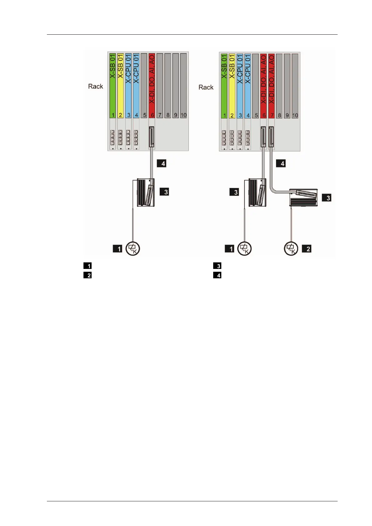
Sensor or Actuator
Redundant Sensor or Actuator
Field Termination Assembly
System Cable
Figure 18: Wiring 3 - Single Connector Board with System Cable
With wiring 3, connector boards of type 03, e.g., X-CB 008 03, are required in the base
plate.
Wiring 4
Connect the sensors or actuators to a redundant connector board with cable plug via field
termination assembly and system cable. The connector board distributes the signal from
one sensor to two redundant modules or merges the signals from two redundant modules
to one actuator.
For this wiring, the redundant system bus and the redundant power supply must be
ensured.
Connect the individual sensors or actuators to a redundant connector board wit via field
termination assembly. In doing so, insert the I/O modules into adjacent slots.