HIMax System 9 Lifecycle
HI 801 001 E Rev. 4.01 Page 93 of 122
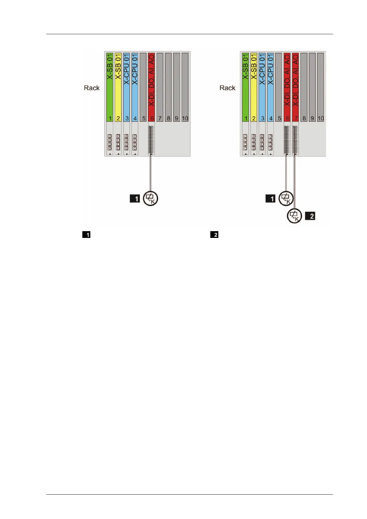
Sensor or Actuator Redundant Sensor or Actuator
Figure 16: Wiring 1 - Single Connector Board with Screw Terminals
With wiring 1, connector boards of type 01, e.g., X-CB 008 01, are required in the base
plate.
Wiring 2
Connect the sensors or actuators to a redundant connector board with screw terminals. The
connector board distributes the signals from one sensor to two redundant modules or
merges the signals from two redundant modules to one actuator.
For this wiring, the redundant system bus and the redundant power supply must be
ensured.
Connect the individual sensors or actuators on a per channel basis to a redundant con-
nector board on which the I/O modules are mounted adjacently.