9 Lifecycle HIMax System
HI 801 001 E Rev. 4.01 Page 106 of 122
Remark to the Standards
The temperature within a housing can also be calculated in accordance with VDE 0660,
Part 507 (HD 528 S2).
i
All considerations about heat must take every component within a cabinet or enclosure into
account, also components that are not directly part of the HIMax system!
Temperature State/Operating Temperature
The controllers are intended for operation up to a maximum temperature of 60 °C. The
temperature states of the individual modules or controllers are centrally evaluated by the
processor module.
A temperature sensor located on a specific temperature-relevant position independently
detects and continuously monitors the temperature state on the corresponding module.
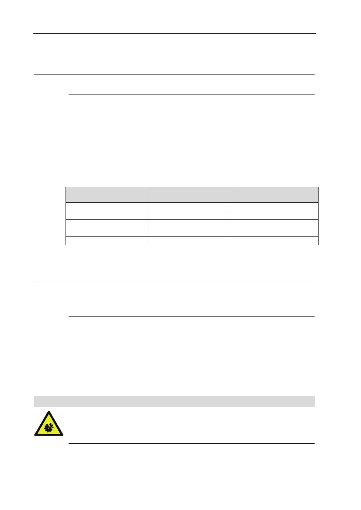
Use the Temperature State system variable in SILworX to evaluate the temperature states.
The Temperature State system variable indicates the operating temperatures measured in
the following temperature ranges:
Ambient temperature,
approx.
Temperature State
System variable values
Temperature State [BYTE]
< 40 °C Normal 0x00
40...60 °C Threshold 1 exceeded 0x01
> 60 °C Threshold 2 exceeded 0x03
Back to 60°C...40°C Threshold 1 exceeded 0x01
Back to 40 °C Normal 0x00
Table 48: Temperature States
If a temperature sensor detects that the temperature exceeds a specific threshold or falls
below it, the temperature state changes.
i
Under unfavorable operating conditions, the Temperature State system variable can even
enter the High Temperature or Very High Temperature state at lower temperatures than
those specified in in
Table 48.
Example after a fan failure.
For each base plate, it is possible to define the temperature threshold that should cause a
message when it is exceeded. In the SILworX Hardware Editor, use the detail view for the
base plate to configure this setting.
9.2 Start-Up
Only power up the system after the hardware is completely mounted and all the cables are
connected. First start up the control cabinet, the the PES itself.
NOTE
System damage possible!
System damage caused by safety-related automation systems improperly connected
or programmed.
Check all connections and test the entire system before starting up!