HIMax System 3 Product Description
HI 801 001 E Rev. 4.01 Page 33 of 122
3.3 Modules and Connector Boards
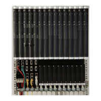
The following module types are available:
Processor modules
for processing the user programs.
System bus modules
for managing the system busses.
Input modules
for measuring and preprocessing the process values.
Output modules
for converting the results of the user program into control commands for actuators.
Communication modules
- for communicating with external devices or systems operating with standard data
transfer protocols (e.g., Modbus, PROFIBUS).
- Physical interfaces for safeethernet for connecting to additional HIMA controllers.
A protective coating protects the electronic module components against corrosion and dust.
Each module forms a functional unit with the connector board. A connector board
establishes the connection between module and field zone or ensures communication to
other controllers or devices.
When replacing a module, the connector board remains in the base plate. In this way, the
cables or wires connected to the connector board need not be released and reconnected.
Each module type is related to one or several types of connector boards.
The connector between I/O modules and the corresponding connector boards are
mechanically coded. This ensures that a module of a certain type can only be plugged in to
the corresponding connector board and prevents them from being equipped with improper
modules. Coding is performed with wedges on the female connector located on the
connector boards, see also the manual for I/O modules.
Two types of connector boards usually exist for I/O modules:
Connector boards for directly connecting to the supply lines of the field devices.
Connector boards for directly connecting field termination assemblies (FTAs)
FTAs are used to connect field devices. They are separated from the controller, e.g., in
their own cabinet.
NOTE
Danger of short-circuit due to insulation damage!
According to UL regulations, only lines suitable for temperatures of at least 75 °C
may be laid next to connector boards and field termination assemblies for X-DO12 01
modules!
For more information on connector boards and field termination assemblies, refer to the
module manuals.
3.3.1 Identifying the Module via SRS
The HIMax system uses the parameters System, Rack, Slot (SRS) to identify the modules.
Designation Range of values Description
System 1...65 535 Resource identification
Rack 0...15 Base plate identification
Slot 1...18 Slot identification
Table 9: Identifying a Module using the System.Rack.Slot

 Loading...