HIMax System 3 Product Description
HI 801 001 E Rev. 4.01 Page 21 of 122
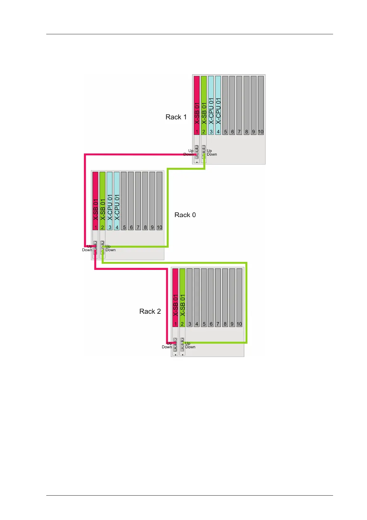
3.2.1 System Bus with Line Structure
Two adjacent base plates can be connected to one base plate.
Figure 3: Arrangement of Racks on the System Bus
A rack sequence results from interconnecting the racks – see
Figure 3.
Start with the rack having rack ID 0.
The extension rack connected to the UP socket of rack 0 has rack ID 1.
- All additional racks connected to rack 0 through rack 1 have uneven rack IDs up to
15.
The extension base plate connected to the DOWN socket of rack 0 has rack ID 2.
- All additional racks connected to rack 0 through rack 2 have even rack IDs up to 14.
3.2.2 System Bus with Network Structure
When operating the system bus in a network structure, the UP, DOWN and DIAG
connectors of the system bus module are equal allowing one to create an arbitrary number