HIMax System 3 Product Description
HI 801 001 E Rev. 4.01 Page 17 of 122
Base plate types:
With 10 slots: X-BASE PLATE 10 01
for mounting on a flat base, e.g., a mounting plate.
With 15 slots: X-BASE PLATE 15 01
for mounting on a backplane
With 15 slots: X-BASE PLATE 15 02
for 19'' mounting
With 18 slots: X-BASE PLATE 18 01
for mounting on a backplane
A total of one module and one connector board can be plugged in to each slot.
System cables are used to interconnect the base plates.
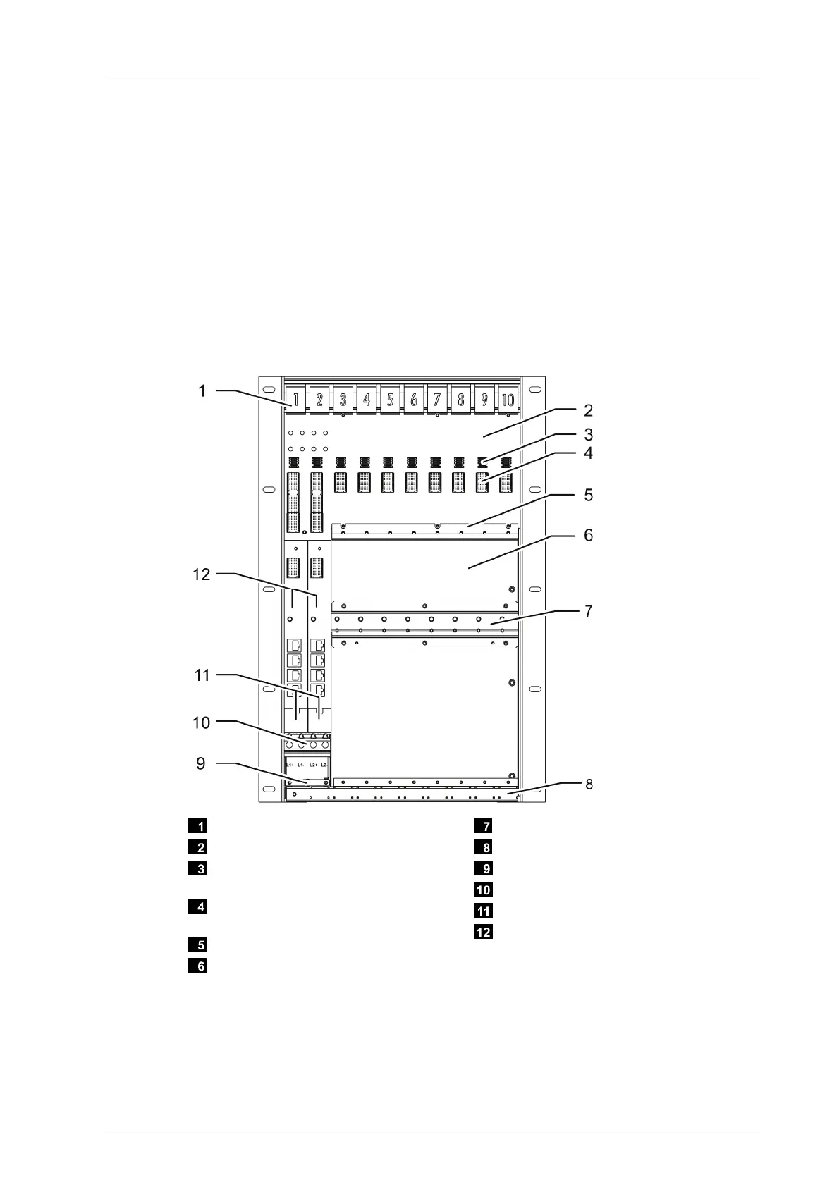
3.1.1 Base Plate Structure
Hook-in rail with slot number
Backplane Bus
Connector for 24 VDC module power
supply, here slot number 9
Connector for connecting the system
bus to a module, here slot number 9
Guiding Rail for Connector Boards
Backplane with wall flanges or 19’’
mounting flanges
Mounting Rail
Cable Shield Rail
Strain Relief for Supply Line
Clamp Terminal Block
Suppressors for High Voltage Transients
Connector Boards for System Bus Mod-
ules
Figure 2: Base Plate Structure
Both left slots, slot 1 and slot 2, are reserved for system bus modules. The remaining slots
can be used for other modules, but observe the restrictions for positioning processor
modules, see Chapter
3.3.2.