3 Product Description HIMax System
HI 801 001 E Rev. 4.01 Page 26 of 122
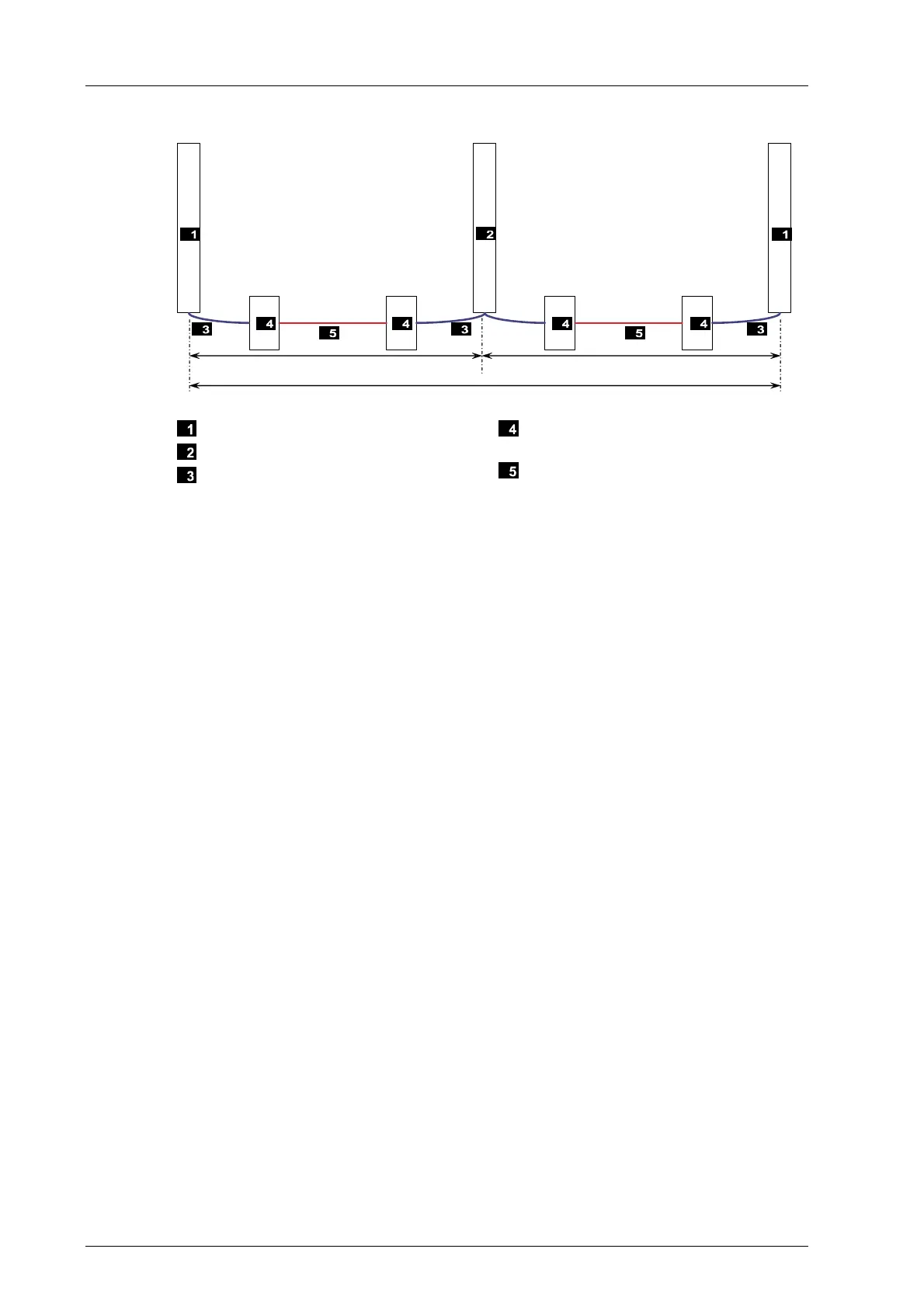
9 800 m
012
9 800 m
19 600 m
Rack with I/O Modules
Base plate with processor modules
Ethernet copper cable
Converter copper cable <-> Fiber optic
cable
Fiber optic cable
Figure 5: Maximum distance for latency default value
The delay time between processor modules and, for instance, the left base plate with I/O
modules is composed of the delay due to the converter (1 µs) and the delay due to the fiber
optic cable length (max. 50 µs - 1 µs). The following formula applies to the delay due to the
fiber optic cable and its length:
49 µs ≥ length * 5 µs / km, i.e., length ≤ 9 800 m
The same formula applies to the length between processor modules and the right rack with
I/O modules, the maximum length of the fiber optic cable is also 9 800 m.
Maximum Distance between Processor Modules.
If the processor modules are distributed among rack 0 and rack 1, these racks can be
positioned far from one another and interconnected using fiber optic cables (
Figure 6).
The two racks with processor modules may be located up to 1.8 km far from one another.
In this case, the HIMax system can have a maximum extension of 17.4 km.