HIMax System 5 Programming
HI 801 001 E Rev. 4.01 Page 59 of 122
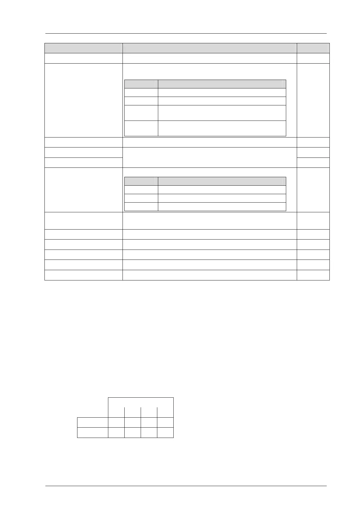
Variable Description Data type
Start Cycle TRUE during the first cycle after starting, otherwise FALSE BOOL
Power Supply State [1]...[4]
Bit-coded state of the power supply units in the processor mod-
ules 1...4
Bit no. State when bit is set
0 Power supply rail 1, faulty
1 Power supply rail 2, faulty
2
Internally generated voltage too high or too
low (overvoltage/low voltage)
3
Invalid adjustment data for the internally
generated voltages
BYTE
System ID System ID of the controller, 1...65535 UINT
Systemtick HIGH UDINT
Systemtick LOW
Circular millisecond counter (64 bit)
UDINT
Temperature State [1] ...[4] Bit-coded temperature state of processor modules 1...4
Bit no. State when bit is set
0 Temperature threshold 1 exceeded
1 Temperature threshold 2 exceeded
2 Incorrect temperature value
BYTE
Remaining Global Force
Duration [ms]
Time in ms until the time limit set for global forcing expires. DINT
CPU Watchdog Time [ms] Maximum permissible duration of a cycle in ms. UDINT
Cycle Time, last [ms] Current cycle time in ms UDINT
Cycle Time, max [ms] Maximum cycle time in ms UDINT
Cycle Time, min [ms] Minimum cycle time in ms UDINT
Cycle Time, average [ms] Average cycle time in ms UDINT
Table 18: Hardware System Variables for Reading the Parameters
The following system variables taking from
Table 18 are arrays. Their index is the
processor module number:
OS Major, OS Minor
Redundancy Info (bit bar)
Power Supply State
Temperature State
The processor module index used in these fields is mapped onto the slots of the processor
modules in the base plates as specified below:
1. In base plate 0, the index is counted in ascending order starting with slot 3.
2. In base plate 1, the index is counted in descending order down to slot 3.
The following assignment results:
Slots
3 4 5 6
Rack 1 4 3
Rack 0 1 2 3 4
Table 19: Assigning the Index to Processor Module Slots
Processor modules with indexes 3 and 4 can either be located in rack 0 or rack 1!