7 Diagnosis HIMax System
HI 801 001 E Rev. 4.01 Page 90 of 122
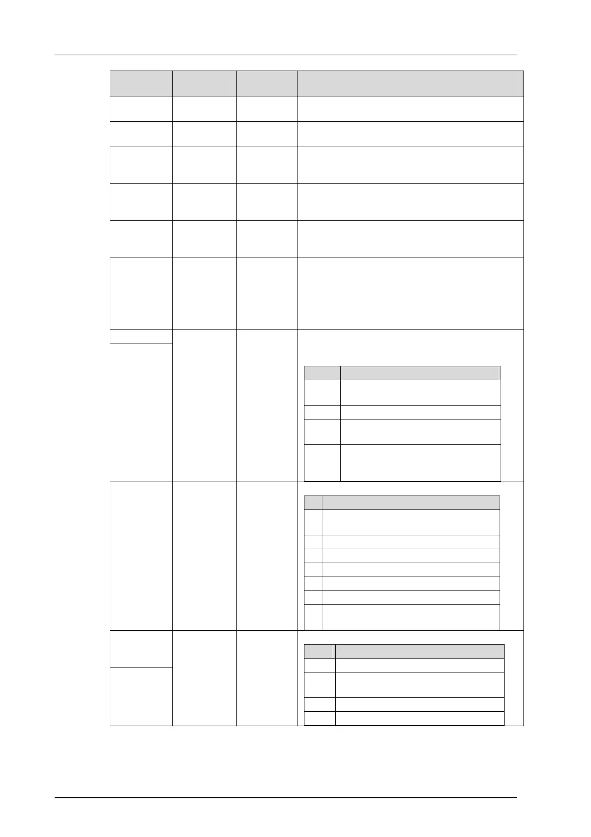
Information
Representa-
tion
Range of
values
Description
S.R.S
Three deci-
mals
0...65535,
0...15, 1...18
Module identification
Module state Text
e.g., STOP,
RUN
State text indicating the operating state of the
module.
Inserted
module
Text
Permissible
module
types
Type of the module actually inserted in the base
plate.
Configured
module
Text
Permissible
module
types
Type of the module planned in the project cur-
rently loaded.
Module type
in project
Text
Permissible
module
types
Type of the module planned in SILworX.
Connection
status
Hexadecimal
value
16#00...0F
Status of the connection between each of the
processor modules (max. 4) and the module.
Each of the bits 0..3 shows the connection to the
processor module with the corresponding index.
The value 1 of the bit means "connected" while
the value 0 means "not connected ".
Send status
Receive
status
Hexadecimal
value
16#0000...F
FFF
Every two bits represents the state of the inter-
face with an index. Bits 0 and 1 apply to interface
0, and so on.
Value Description
00
No message received/sent yet,
unknown status
01 OK, no faults
10
Las reception/transmission was
defective
11
No faults during last recep-
tion/transmission, one fault oc-
curred before
Module
status
Hexadecimal
value
16#00...3F Bit-coded module status
Bit Meaning with value = 1
0
Warning related to external communi-
cation.
1 Warning related to field connection
2 System warning
3 External communication error
4 Field connection error
5 System error
6-
7
Not used
Status of
system bus
A
Status of
system bus
B
Hexadecimal
value
16#0...3 Status of the interface to system bus A/B:
Value Description
0 The interface is OK
1
The interface detected an error dur-
ing last reception, now it is OK.
2 An error occurred on the interface.
3 The interface is switched off.
Table 42: Diagnostic Information Displayed in the Online View for the Hardware Editor