7
────────────────────────────────────────────────────
1.3 Measurements and Working Systems
────────────────────────────────────────────────────
r
2
r
1
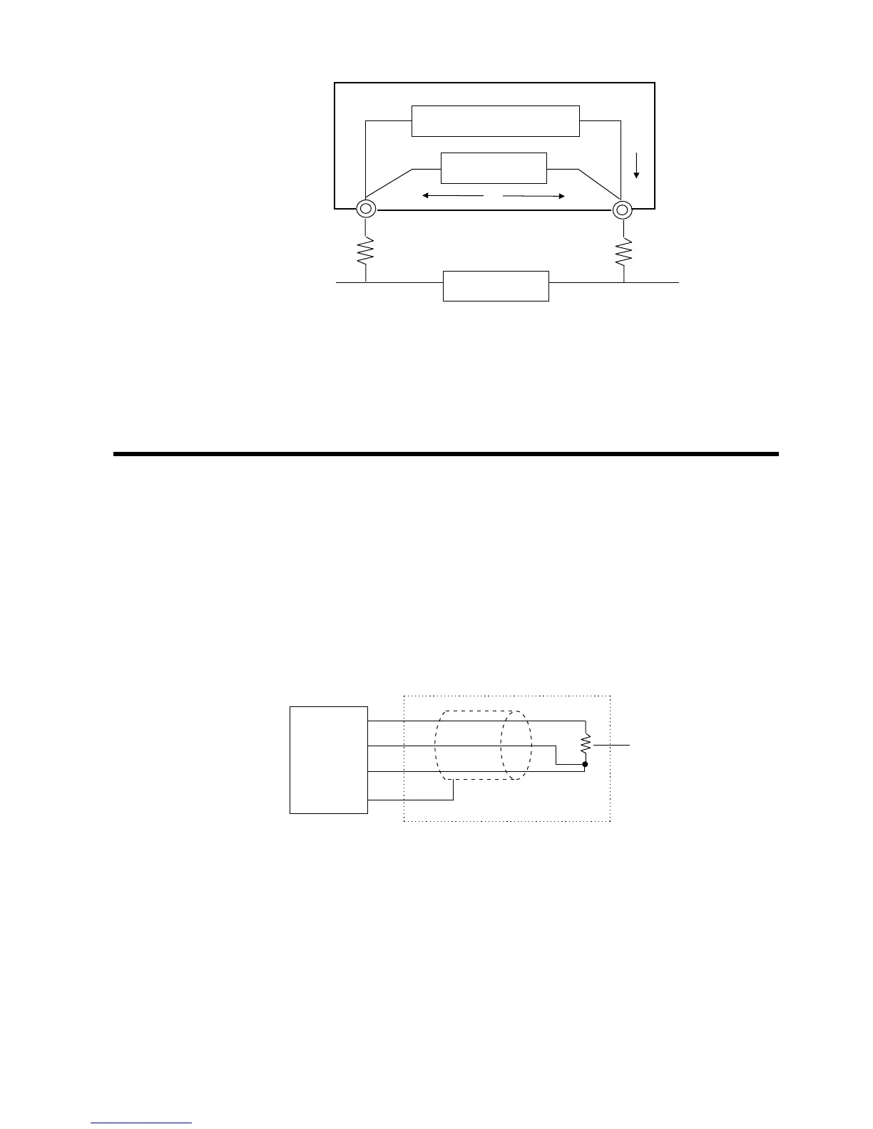
The Internal Circuit of the Temperature Probe
The current I flows to the measured resistance R
0
and the wiring resistance r
1
and r
2
. Therefore, the measuring voltage E can be obtained by E=I(r
1
+R
0
+r
2
),
and it would include the wiring resistance r
1
and r
2
.
The 9188 TEMPERATURE PROBE makes temperature measurement and the
temperature correction function easy. In this section, explain the principle of
them.
See Section 3.4.2, "Temperature Correction and Temperature Measurement",
for connecting the temperature probe.
(1) Temperature measurement
The internal circuit of the temperature probe is as follows.
The temperature probe uses the platinum film resistor which is changeable
according to the temperature, as the temperature sensor. This probe displays
the resistance value of that register, detected by the 3227, after converting it
to the temperature using the CPU.