54
────────────────────────────────────────────────────
6.3 Electrical Specifications
────────────────────────────────────────────────────
RANGE
―――――――――
Resistance
measurement range
RANGE
―――――――――
Resistance
measurement range
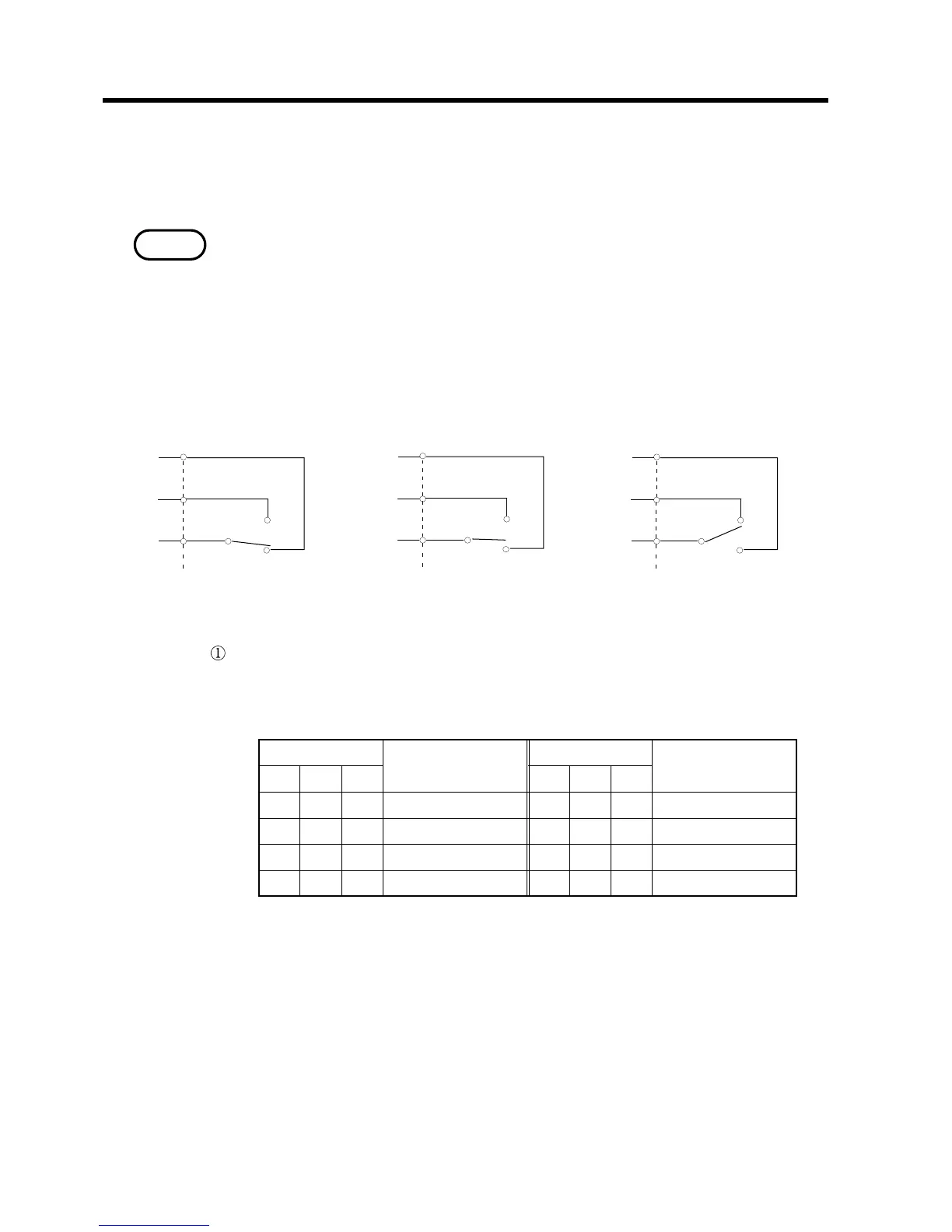
2 1 0 2 1 0
H H H No change L H H 300 Ω
H H L 300 mΩ L H L 3kΩ
H L H 3 Ω L L H 30 kΩ
H L L 30 Ω L L L 300 kΩ
The functions according to the state of input and output are shown below. See
Section 6.4, "Signal Timing", for such as the detailed timing.
The external control terminal is valid only in the resistance measurement
mode, except the print requiring input signal (PRINT
―――――――
). In the temperature
measurement mode the input signals except print requiring (PRINT
―――――――
) are
invalid and each functions are not executed. The output signal keeps the state
before changing to the temperature measurement mode and does not change
during the temperature measuremnt mode.
(1) Input signal
During explaining following input signals, "H"or "L"show following state.
Selecting the measuring range (RANGE 0
――――――――――
to RANGE 2
――――――――――
)
Select the measuring range followingly during the resistance measurement.
See Section 4.3.2, "Selecting the Measuring Range", for the measurment
range.