7.4 Using the Software
索引
4
3
2
1
7
6
5
10
9
8
Connecting with a Computer
4.
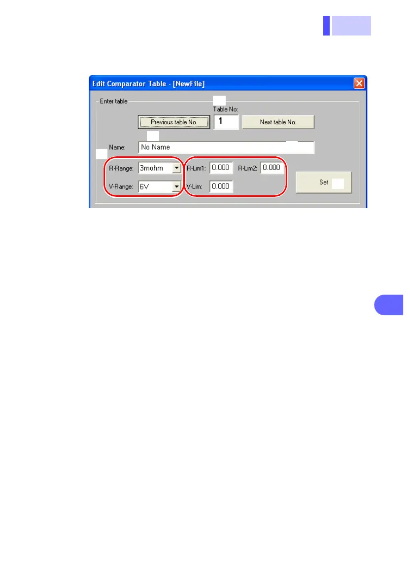
Entering configurations for each table.
(In the illustration above, resistance upper limit no. 1 has
been set at 130.0 mΩ, resistance upper limit no. 2 at 140.0
mΩ [300 mΩ range], and the voltage lower limit has been
set at 1.500 V [6 V range]).
(1) Enter the table no.
This number can be selected by clicking [Previous
table No.] or [Next table No.], or by clicking on the
table.
(2) Enter the name to be assigned to the table no.
If no name is entered, the default value "No Name"
will be used.
(3) Set the resistance and voltage ranges.
(4) Enter resistance upper limit no. 1 (R-Lim 1), resis-
tance upper limit no. 2 (R-Lim 2), and the voltage
lower limit (V-Lim).
Enter resistance input values in units of mΩ.
<Ex.>
When entering 6.25 mΩ in the 30 mΩ range, enter
"6.25".
When entering 1.5 Ω in the 3 Ω range, enter "1500".
(5) Finalize the settings.
Configure all tables by repeating steps (1) - (5) above.
5.
Save these configurations to a file by clicking [Save].
See "Section 7.4.7 Transferring Tables of Permissible
Values" (⇒ p.115) for details of transferring tables of per-
missible values.
(1)
(2)
(3)
(5)
(4)