10.5 Synchronous Detection System
索引
4
3
2
1
7
6
5
10
9
8
Appendix
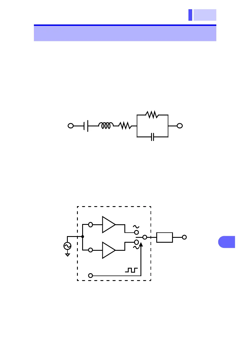
The figure below shows an equivalent circuit for a battery. If the
measured object exhibits other electrical characteristics in addi-
tion to resistance, as shown in this figure, we can use the syn-
chronous detection system to obtain the effective resistance of
the object. This synchronous detection system is also used to
separate faint signals from noise.
The synchronous detection system picks up the reference signal
and those signals having the same phase components. The fig-
ure below gives a simplified schematic diagram of the synchro-
nous detection system. The system consists of a multiplying
circuit that multiplies two signals and a low-pass filter (LPF) that
picks up only DC components from the output.
10.5 Synchronous Detection System
L
R
2
C
R
1
E
Non-inversion amplifier
Inversion amplifier
Reference signal
-1
Low-pass filter
+1
LPF
Multiplier circuit