3.3 Zero-adjustment
3.3.1 Shorting Methods for Various Test Leads
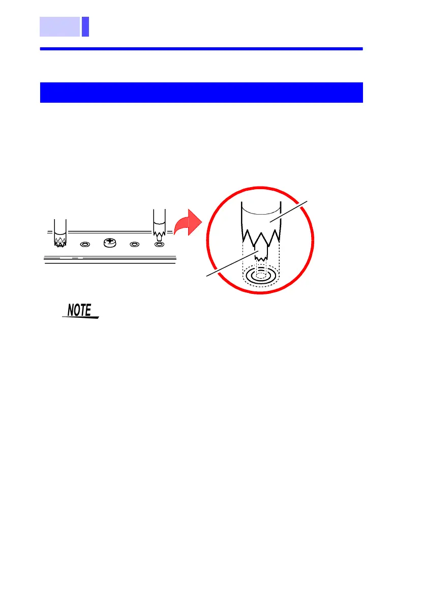
Short the test leads using the four-terminal AC method, with the
included zero-adjust board. As shown in the illustration below,
select a hole suited to the distance between terminals on the
battery subject to measurement. Press it in a way symmetrical to
the central screw on the zero-adjust board. Keep the zero-adjust
board at least 10 centimeters away from the instrument.
Model 9465-10 PIN TYPE LEAD
SOURCE
SENSE
Zero adjustment board
• Be sure to use the included zero-adjust board for
the zero-adjust feature. Also, be sure to connect
each of the SOURCE and SENSE terminals by
inserting the tip of the pin into the holes on the
zero-adjust board as shown in the illustration.
• Do not place the zero-adjust board on top of the
battery or any pieces of metal. Electromagnetic
induction effects could result in unstable measure-
ment values. In such a case, separate the zero-
adjust board from any metal components.
• Conducting zero adjustment by connecting the
tips of pin-type leads or using a metal sheet other
than the included zero-adjust board will result in
inaccurate adjustment.
• When the distance between the terminals on the
battery subject to measurement is greater than
the distance between the holes on the zero-
adjust board, use the holes in the corners for the
zero-adjust feature.