4.3 Setting Comparator Permissible Values
Judgment is conducted using the display and the buzzer, as
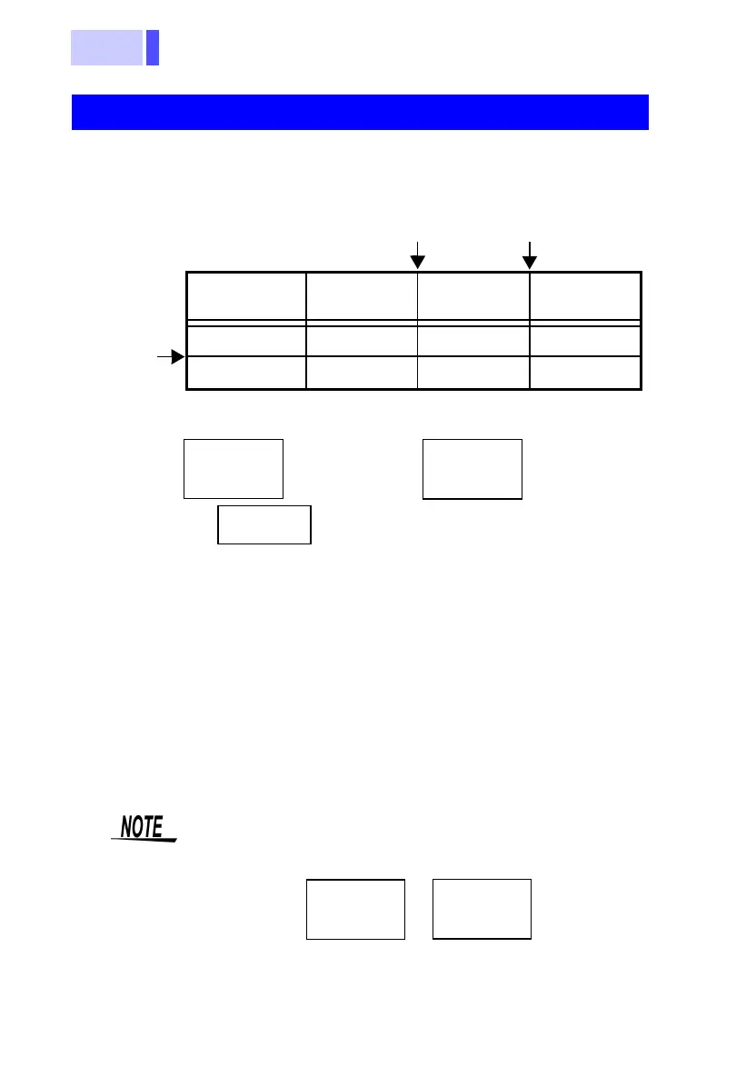
shown in the following table:
Boundary conditions are shown below:
Examples of how to read the comparator output table
<Ex. 1>
When the measured resistance value does not
exceed resistance upper limit no. 1 and the mea-
sured voltage value is greater than the voltage
lower limit, "Pass" will be displayed.
<Ex. 2> When the measured resistance value exceeds the
resistance upper limit no. 1 and does not exceed
the resistance upper limit no. 2, and the measured
voltage value is greater than the voltage lower
limit, "Warning" will be displayed and a buzzer
sounded.
Comparator Comparison Table
Resistance
(low)
Resistance
(medium)
Resistance
(high)
Voltage (high) PASS WARN FAIL
Voltage (low) WARN WARN FAIL
Resistance upper
limit no. 1
Voltage
lower limit
Resistance uppe
limit no. 2
Voltage WARN
<
Voltage
lower limit
≤ Voltage PASS
PASS
Resistance
upper limit
no. 1
≤
WARN
<
Resistance
upper limit
no. 2
≤
FAIL
<
When the resistance upper limit no. 1 and no. 2
are set at the same value, the boundary conditions
will be as shown below:
esistance
ASS
Resistance
upper limit
no. 1
≤
Resistance
upper limit
no. 2
Resistanc
FAIL
<
=
 Loading...


