8
Unit Installation
7. Unit Installation
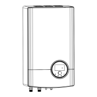
7.1 MAIN PARTS (DESCRIPTIONS)
No. Part
2
3
4
5
1
6
8
1 Upper front panel
2 Lower front panel
3 Side panel
4 Master controller
5 Piping connections
6 Hole for wiring
7
Window for charge
port of expansion
vessel
8
Window for
air purge valve
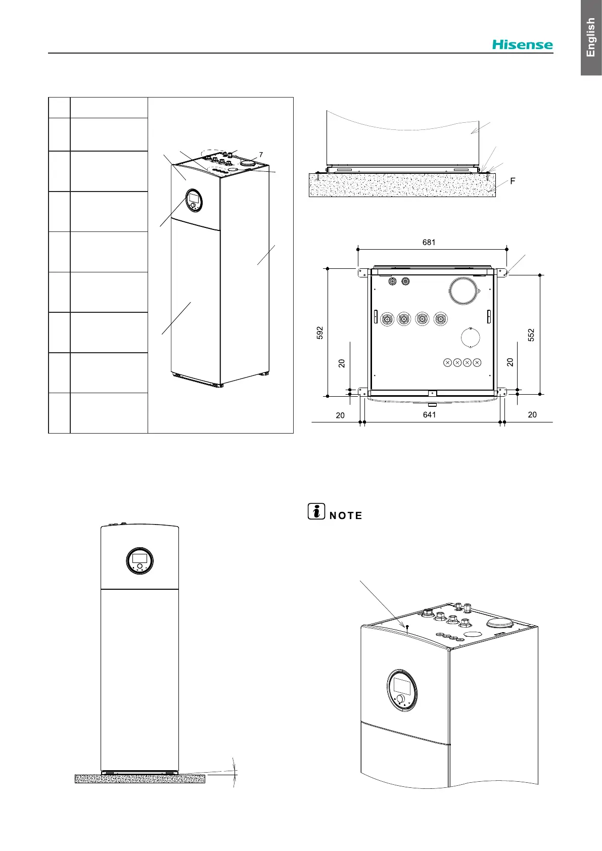
7.2 UNIT INSTALLATION
irregularities. The maximum allowed deviation is 1°.
Unscrew the 1 screw.
To prevent the indoor unit from tipping, it is
L-shaped feet with 8 anchor bolts (M6).
Unit: mm
≤1°
loor
Indoor unit
L-shaped feet
(4 parts)
Anchor bolts
(8)
∅7×8
7.3 REMOVING THE PANELS
If it is necessary to access to the indoor unit components,
please follow these operations.
The indoor unit front panel needs to be removed for any task
inside the indoor unit.
7.3.1 Removing the upper front panel
1. Unscrew 1 screw on the top of unit.