16 301C User Manual 510324
Honeywell 4/07
Introduction
Wiring Details
Wiring Details
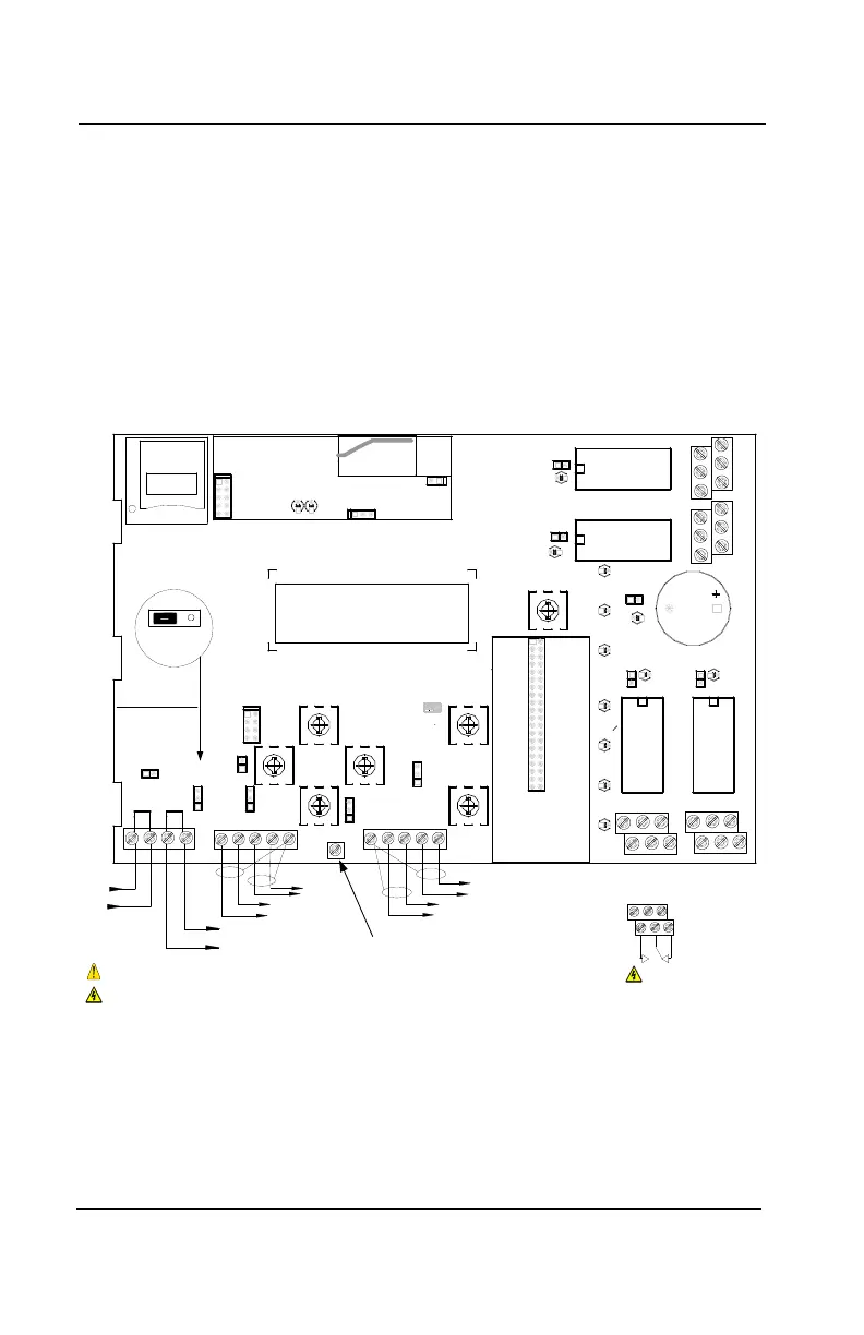
The diagram below provides the details required to connect the 301C
with the wireless communication module (coordinator). This module
allows the controller to communicate with and manage the 301W
wireless gas detectors.
Details concerning power supply, cables, capacities, etc., are provided
in the Specifications section at the back of this manual.
COMMUNICATION
Communication Wire Gauge:
2-24 AWG (Belden 9841)
Twisted and shielded cable
2000 feet (600 m) per channel
T-tap: 65 feet (20 m) / T-tap
130 feet (40 m) total
Channel Specifications:
Channel 1-2: Modbus,Vulbus protocol
Channel 3: Modbus protocol only
Communicates only with Vulcain
transmitters
Channel 4: Modbus output
Communicates only with VA 301BDCM
*No transmitter can be connected to
channel 4
Channel 4
Channel 3
A 4
B 4
A 3
B 3
Channel 2
Channel 1
B 2
A 2
A 1
B 1
V-
NEXT
V+
PREVIOUS
V-
V+
509521
RESET
PCB301CWRA
SHIELD
SHIELD
SHDN
V+
B4A4B3A3
B2A2
RIGHT
LEFT
RX
TX
ALARM_A
B1
A1
V-
ALARM_B
ALARM_C
POWER
FAULT
DOWN
ENTER
ESC
SILENCE
N.C.
N.O.
N.O. N.C.
UP
MADE IN CANADA
RC
RC
RC
RC
R
R
R
R
RELAY # 1
RELAY # 2
RELAY # 4
RELAY # 3
Vin Vout
1
ETHERNET MODULE
V-V+
J30
J4
J32
J31
J29
R6
LED5
LED1
LED2
LED11
LED10
C41
SW8
SW3
SW5
SW6
SW7
SW2
LED18
LED17
LED15
LED7
LED4
LED3
LED13
K4
J23
J26
J25
EOL1
EOL4
EOL3
EOL2
BZ1
J7
J3
J10
J24
J22
J13
J27
K2
K1
L2
R3
J6
SW1
J36
K3
Made in Canada
Vulcain Inc.
509883
VA301CWPRB
RESET
J2
J1
D1
D2
JP1
L10
N.C.
N.O.
N.O.
Ethernet: 10/100-compatible with 10Base-T
interface, RJ-45
Visual Indicators:
Green LED LINK
Yellow LED ACT
BacNet/IP MODULE (-BIP option)
Always respect minimum
voltage requirements at device
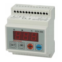
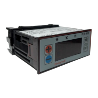
LCD screen
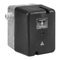
Wireless
communication module
Wireless Communication:
ISM worldwide
Indoor range 30m
RELAY OUTPUTS
3+5
4+6
1+3
2+4
Normally
open
Normally
closed
5
31
642
RISK OF ELECTRIC SHOCK
RISK OF ELECTRIC SHOCK
End-of-line specification:
The E.O.L. jumper for
channels 1-2-3-4 must
always be in E.O.L.
position.
End-of-line jumper
position
RC
R
SD Card
Grounding screw

 Loading...