ALPHABETIC REFERENCE EXCEL CARE CONTROL ICONS
74-5577–33 (US) 104
EN2B-0184 GE51 R0518 (Europe)
Freeze Time Function
(Ideal Curve and
Extrapolation only) The freeze time function (only for the Ideal Curve and Extrapolation algorithms) is
initiated at the beginning of every measurement interval (window) and ends after the
time set in Parameter P11 has elapsed. During the freeze time, no power value to
switch the loads (to the output Po1/2/3) is issued, but the calculation algorithm
continues to run normally.
This function is used to prevent incorrect (too early) load switching at the beginning
of every measurement interval. The minimum duration of the freeze time (minimum
value of Parameter P11) is preset to 30 seconds and should not be set to a value
less than 30 seconds at run time.
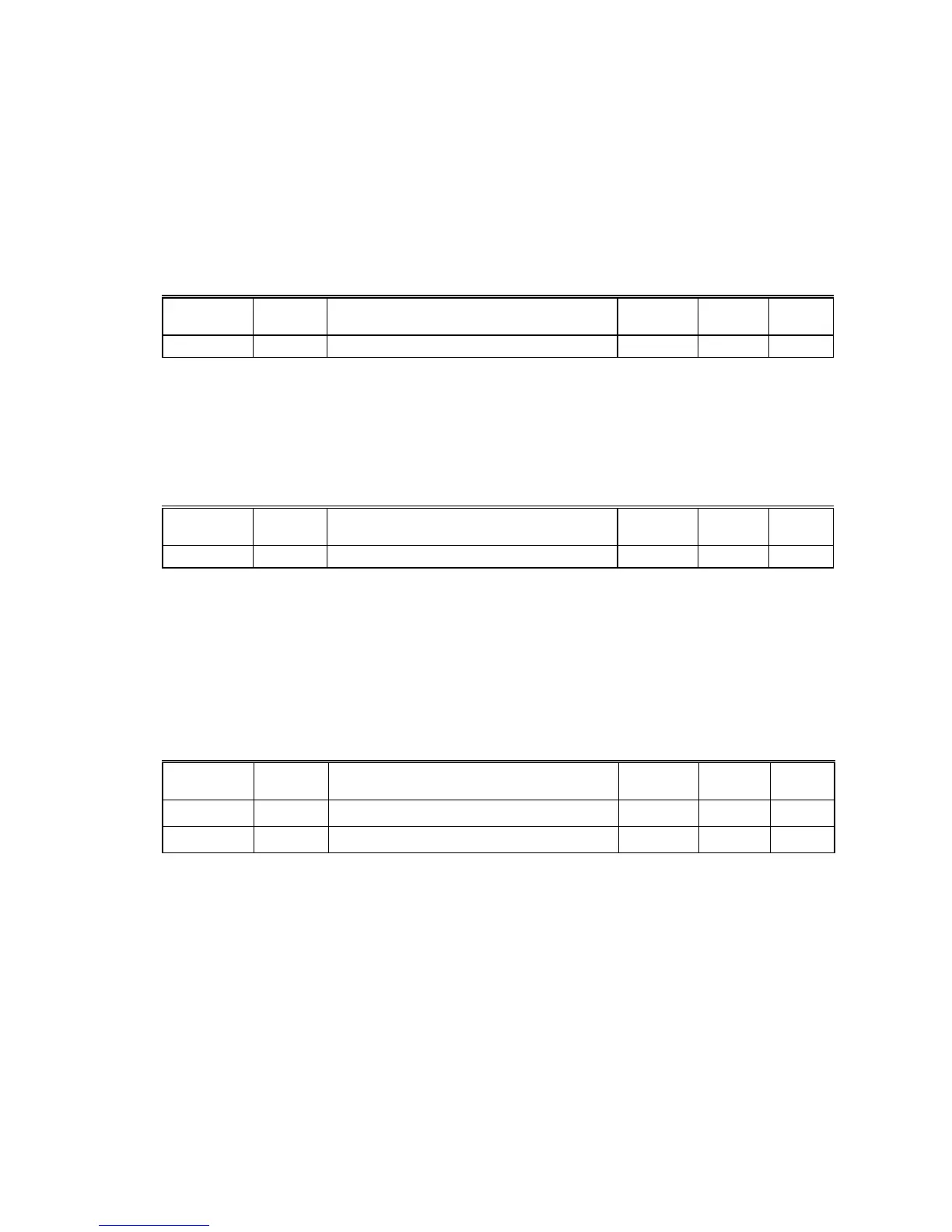
The following tables describes the parameter used for the freeze time function.
Parameter
Number
Type
Brief Description
Setting
Range
Default
Value
Unit
11 Comm. Freeze Time (not for Sliding Window) 30-300 180 sec
Switch-on Wait Time The switch-on wait time function is valid for all power calculation algorithms and is
initiated by the transition of the calculated switching power from a negative to a
positive value. Parameter P12 sets the duration of the switch-on wait time.
This function provides controlled switching ON of loads after the calculation
procedure makes a transition from shedding loads to restoring loads.
The following table describes the parameter used for the switch-on wait time.
Parameter
Number
Type
Brief Description
Setting
Range
Default
Value
Unit
12 Comm. Switch-on Wait Time 0-240 120 sec
Power Limit Setpoint
Switchover Either of two power limit (demand) setpoint values (Parameter P13 or P14) can be
used depending on the value (0 or 1) of the internal user address ID___Tariff. The
value 0 at ID___Tariff switches the power limit setpoint Parameter P13 to the power
calculation algorithm, while the value 1 switches Parameter P14.
A simple application for this switchover function is a Time Program that uses
ID___Tariff to switch between power limit Parameters P13 and P14, depending on
the time of day.
The following table lists parameters used for the power limit switchover function.
Parameter
Number
Type
Brief Description
Setting
Range
Default
Value
Unit
13 Comm. Power Limit 1
0-10
6
10000 kW
14 Comm. Power Limit 2
0-10
6
10000 kW
Switching Behavior of
Loads in a Priority Group You can select one of two switching behaviors for each priority group by setting the
Parameters P15 for group 1, P16 for group 2, and P17 for group 3.
The first switching behavior (P15/16/17 is set to 0) is the sequential switching of
loads according to the load number (P14 of XFM 36-1) of a load XFM 36-1 within a
priority group. Load number 1 is switched on at first and the loads number 2. 3, - 50
are switched on in a group 1/2/3. The switched-on load with the highest number is
switched off and shed first. Make sure that loads are numbered accordingly
(Parameter 14 in XFM 36-1.)
The second switching behavior (P15/16/17 is set to 1) is the rotating switching of
loads according to their measured times of being On or Off. The load that has been

 Loading...


