3.2.17.2 Creating nozzle proles (optional)
A certain combination of active nozzles is referred to as "nozzle prole".
Up to 16 dierent nozzle proles can be created. The nozzle proles to be used for the automatic
nozzle control must be dened hereby.
F
a
b
c d
f
e
a
g
h
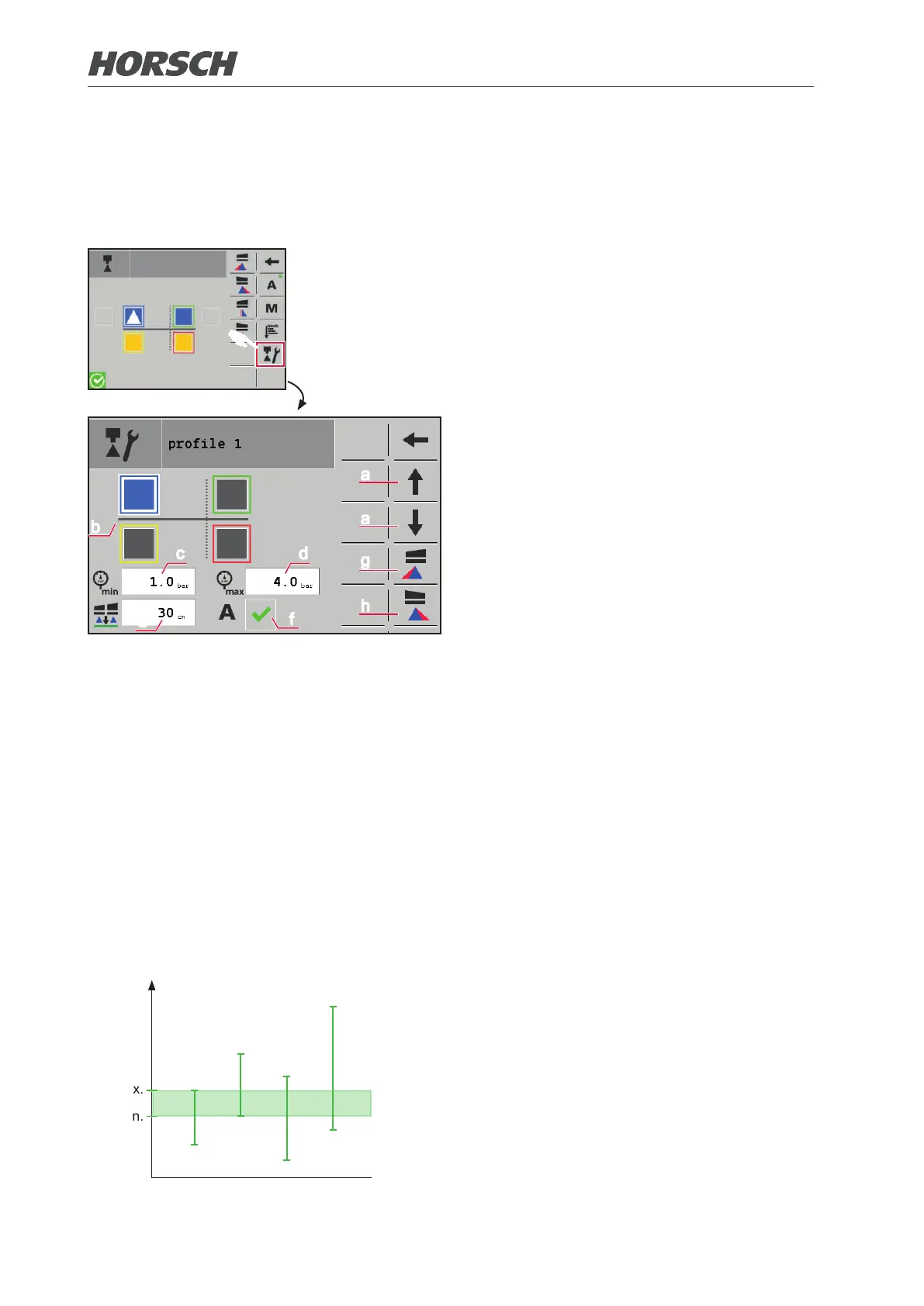
¾ Select the "prole" screen and access the
prole via the arrows (a).
¾ Select the nozzles to be active in the prole
by touching (b).
If a nozzle is activated the eld is displayed
in the colour of the nozzle entered.
¾ Enter the pressure range of the prole.
The pressure range is determined by indi-
vidual nozzles:
The minimum pressure of the prole corre-
sponds to that of the nozzle with the highest
permissible minimum pressure (c).
The maximum pressure of the prole corre-
sponds to that of the nozzle with the lowest
permissible maximum pressure (d).
¾ Determine the height of the folding boom
above the crop (e). This value is selected
when using the prole.
¾ Activate the prole in eld (f) if it shall be
used with automatic nozzle control.
¾ A pre-selection can be made for each prole
whether the left (g) and/or the right (h) border
nozzle shall be activated.
¾ Access and create additional proles via
the buttons (a) if applicable.
Pressure
max.
min.
Nozzle 1
Nozzle 2
Nozzle 3
Nozzle 4
Pressure ranges
The pressure ranges of the individual nozzles
are shown by way of example in the adjacent
diagram (vertical dashes).
The minimum pressure and maximum pres-
sure of the prole is derived from the inter-
section of this pressure ranges (green area).
42 43