60
Table 9 Selection of the optimum configuration BPDU
Step Actions
1
Upon receiving a configuration BPDU on a port, the device compares the priority of the received
configuration BPDU with that of the configuration BPDU generated by the port, and:
• If the former priority is lower, the device discards the received configuration BPDU and keeps
the configuration BPDU the port generated.
• If the former priority is higher, the device replaces the content of the configuration BPDU
generated by the port with the content of the received configuration BPDU.
2
The device compares the configuration BPDUs of all the ports and chooses the optimum
configuration BPDU.
The following are the principles of configuration BPDU comparison:
{ The configuration BPDU with the lowest root bridge ID has the highest priority.
{ If configuration BPDUs have the same root bridge ID, their root path costs are compared. For
example, the root path cost in a configuration BPDU plus the path cost of a receiving port is S.
The configuration BPDU with the smallest S value has the highest priority.
{ If all configuration BPDUs have the same ports value, their designated bridge IDs, designated
port IDs, and the IDs of the receiving ports are compared in sequence. The configuration BPDU
that contains the smallest ID wins.
A tree-shape topology forms when the root bridge, root ports, and designated ports are selected.
Figure 18 de
scribes with an example how the STP algorithm works. This example shows a simplified
spanning tree calculation process.
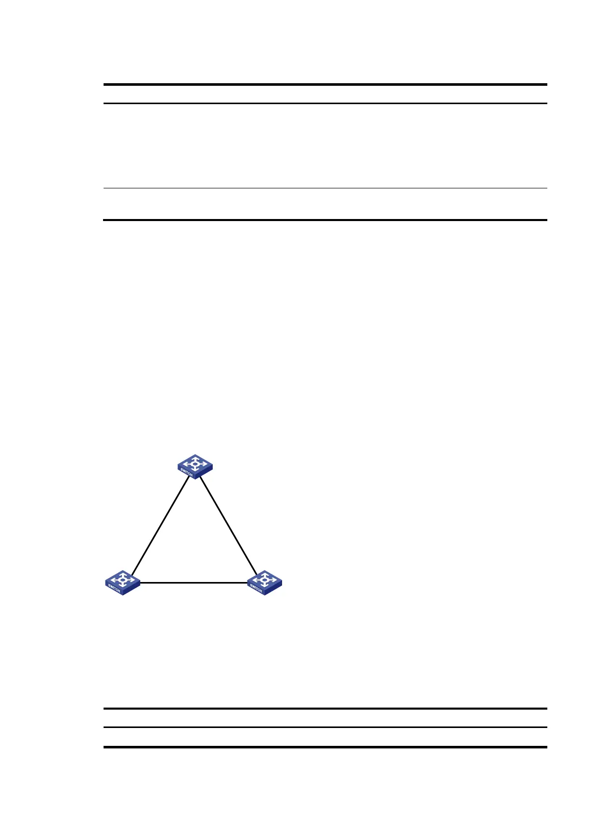
Figure 18 The STP algorithm
As shown in Figure 18, the priority values of Device A, Device B, and Device C are 0, 1, and 2, and the
path costs of links among the three devices are 5, 10, and 4, respectively.
4. Initial state of each device
Table 10 Initial state of each device
Device Port name Confi
uration BPDU
on the
ort
Device A Port A1 {0, 0, 0, Port A1}
Device A
Priority = 0
Device B
Priority = 1
Device C
Priority = 2
Port A1 Port A2
Port B1
Port B2
Port C1
Port C2
P
a
t
h
c
o
s
t
=
5
P
a
t
h
c
o
s
t
=
1
0
Path cost = 4

 Loading...


