Component identification 13
Smart Storage Battery connector
Rear SFF drive backplane detection connector
Front drive cage 2 backplane power connector
Front drive cage 1 backplane power connector
Storage backup power connector for expansion slots 1–2
Power pass-through board connector
Internal USB 3.0 connector
Rear drive cage backplane power connector
32
6 SFF backplane sideband connector
1
The PCIe expansion slots 1-4 and the FlexibleLOM slot are associated with processor 1.
2
The PCIe expansion slots 5-7 are associated with processor 2.
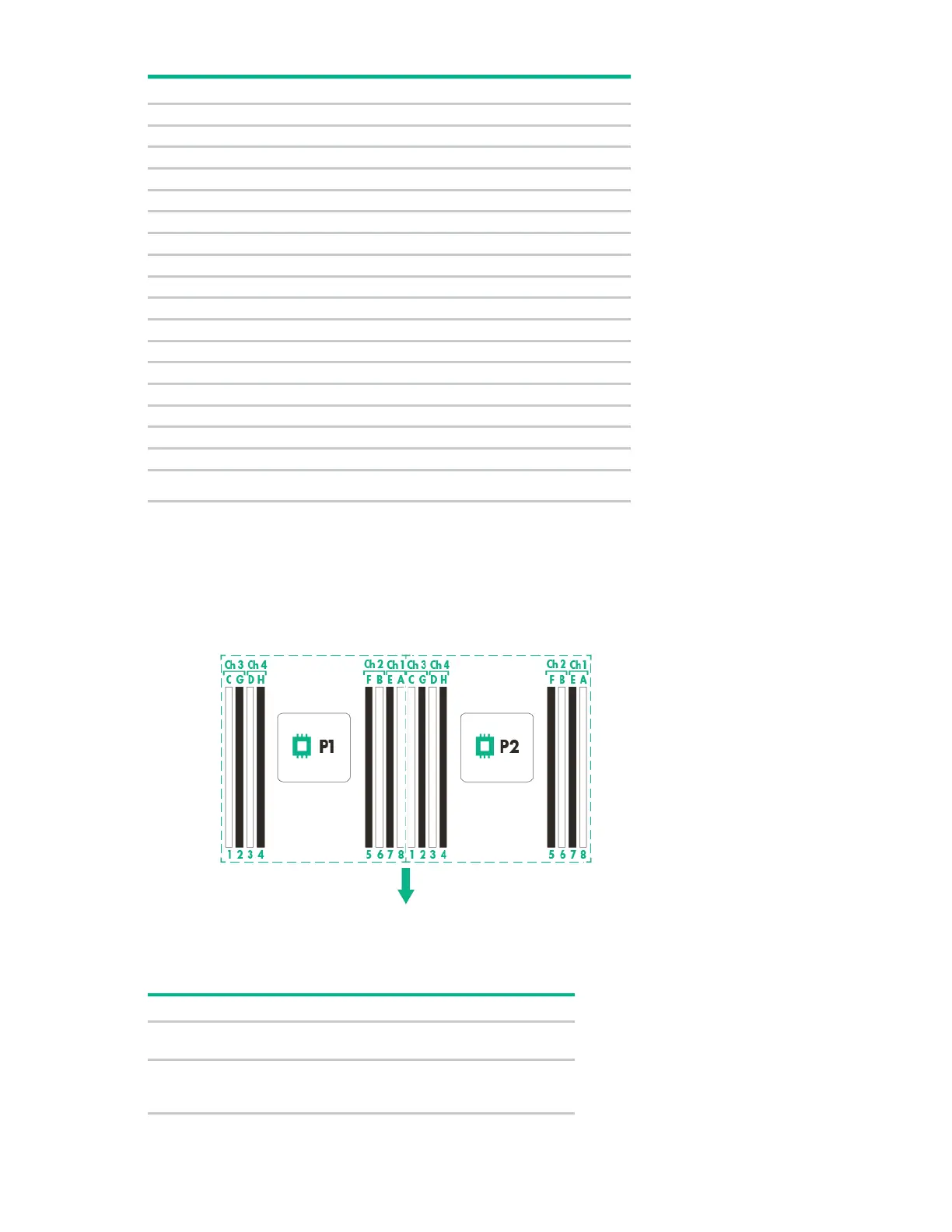
DIMM slot locations
DIMM slots are numbered sequentially (1 through 8) for each processor. The supported AMP modes use
the letter assignments for population guidelines.
The arrow points to the front of the server.
System maintenance switch
Position Default Function
S1
Off = iLO 4 security is enabled.
On = iLO 4 security is disabled.
S2
Off = System configuration can be
changed.
On = System configuration is locked.
 Loading...