Hardware options installation 96
6.
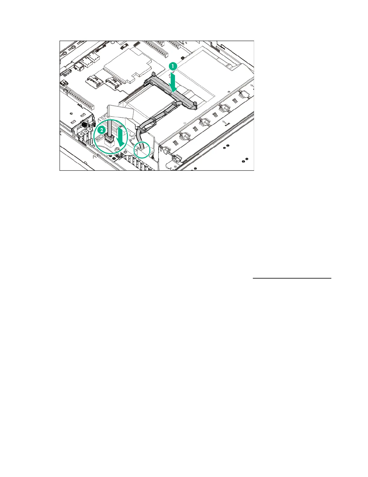
Secure the battery cable on the air baffle clips, and then connect the cable to the system board.
7. Install the access panel (on page 30).
8. Install the server into the rack (on page 45).
9. Power up the server (on page 19).
M.2 SSD enablement board option
The M.2 SSD enablement board is supported in the following expansion slots:
• For standup installation: PCIe3 x8 expansion slot 1, PCIe3 x16 expansion slot 2
• For horizontal installation (two-slot PCI riser cage option required): PCIe3 x8 riser board slots 3 and
4
For more information about product features, specifications, options, configurations, and compatibility,
see the product QuickSpecs on the Hewlett Packard Enterprise website (http://www.hpe.com/info/qs).
Installing the M.2 SSD enablement board
1. Power down the server (on page 19).
2. Remove all power:
a. Disconnect each power cord from the power source.
b. Disconnect each power cord from the server.
3. Remove the server from the rack (on page 28).
4. Remove the access panel (on page 29).
5. Remove the air baffle (on page 30).
6. To install the M.2 SSD enablement board in the onboard expansion slots, do the following:
 Loading...