Component identification 9
Front drive thermal LED
The thermal warning function of the front drive health/thermal LED depends on the iLO 08-HD Max sensor
reading. This function is disabled under these conditions:
• There are no drives in the front drive cages 1 and 2.
• The temperature sensor in one or more front drives has failed.
Under these conditions, iLO shows the 08-HD Max sensor reading as N/A. To view temperature sensor
data, log in to iLO 4 web interface and navigate to the Information → System Information → Temperatures
page.
If the 08-HD Max sensor reading shows N/A, observe the following when extending the front drive cage:
• Do not keep the drive cages out of the chassis for more than 140 sec.
• Keep the drive cages inside the chassis for at least 300 sec before extending them out again.
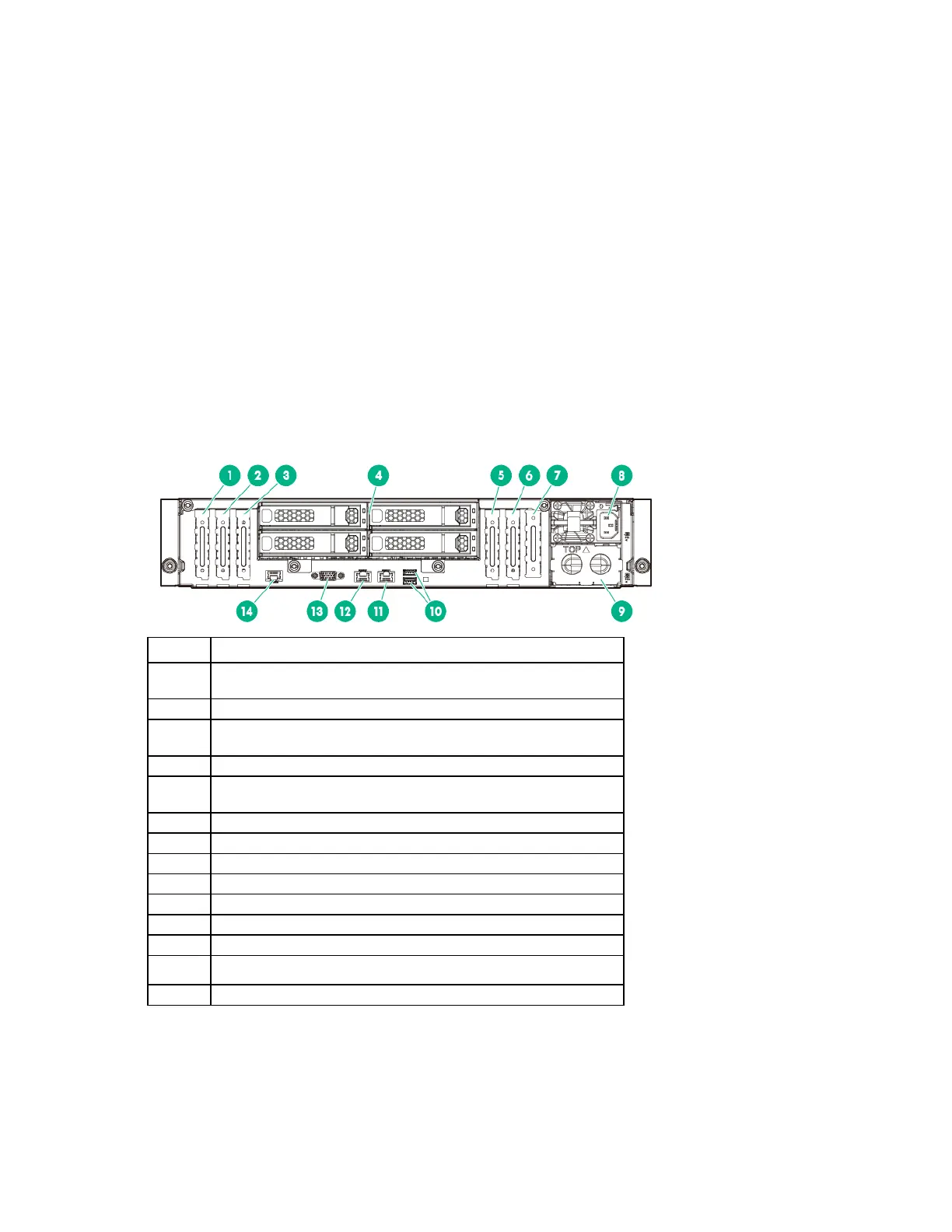
Rear panel components
• Rear panel with the four-bay LFF hot-plug rear drive cage option
1
PCIe3 x16 (16, 8, 4, 1) slot 7 for low-profile, standup expansion
board
1
PCIe3 x8 (8, 4, 1) slot 6 for low-profile, standup expansion board
1
3
PCIe3 x16 (16, 8, 4, 1) slot 5 for low-profile, standup expansion
board
1
5
PCIe3 x16 (16, 8, 4, 1) slot 2 for low-profile, standup expansion
board or riser cage options
2
PCIe3 x8 (8, 4, 1) slot 1 for low-profile, standup expansion board
2
Hot-plug power supply bay 1
Hot-plug power supply bay 2
NIC 1/shared iLO connector
13
Dedicated iLO management connector (optional)
1
The PCIe expansion slots 5-7 are associated with processor 2.
2
The PCIe expansion slots 1-4 and the FlexibleLOM slot are associated with processor 1.
 Loading...