List of Figures
1-1 Server Block Diagram....................................................................................................................21
1-2 I/O Subsystem Block Diagram......................................................................................................22
1-3 Memory Block Diagram................................................................................................................24
1-4 Power Subsystem Block Diagram.................................................................................................25
1-5 Front Panel Controls, Ports, and LEDs..........................................................................................27
1-6 Server Status LEDs........................................................................................................................28
1-7 System Insight Display LEDs........................................................................................................29
1-8 Hot-Pluggable SAS Drive LEDs....................................................................................................30
1-9 DVD LED.......................................................................................................................................31
1-10 Rear Panel Control, Port, and LED Locations...............................................................................32
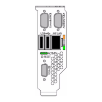
1-11 iLO 2 MP Controls, Ports, and LEDs.............................................................................................32
3-1 Removing a Hard Drive Filler.......................................................................................................46
3-2 Installing a SAS Hard Drive..........................................................................................................47
3-3 Power Supply Location.................................................................................................................48
3-4 Installing a Power Supply.............................................................................................................48
3-5 Removing the Top Cover...............................................................................................................49
3-6 Removing the Airflow Guide........................................................................................................50
3-7 Fan Carrier Handle........................................................................................................................50
3-8 Memory Location and Slot IDs......................................................................................................51
3-9 Processor Cage Handle..................................................................................................................54
3-10 Processor Cage Open.....................................................................................................................54
3-11 ZIF Socket, Alignment Holes and Posts, and Slot Locations........................................................55
3-12 ZIF Socket......................................................................................................................................56
3-13 Processor Power Connectors.........................................................................................................57
3-14 Replacing the Airflow Guide........................................................................................................58
3-15 I/O Backplane Assembly Screw Locations....................................................................................59
3-16 I/O Backplane Assemblies.............................................................................................................60
3-17 SAS Smart Array P400 Controller and PCIe Expansion Board Slots............................................62
3-18 Board Lock.....................................................................................................................................62
3-19 Installing the RAID battery...........................................................................................................63
3-20 Replacing the Top Cover...............................................................................................................64
3-21 Rear Panel Control, Port, and LED Locations...............................................................................66
3-22 iLO 2 MP Setup Flowchart............................................................................................................69
3-23 Web Login Page.............................................................................................................................77
3-24 Status Summary Page....................................................................................................................77
5-1 System Insight Display LEDs......................................................................................................115
6-1 Extending the Server from the Rack............................................................................................143
6-2 Removing the Top Cover.............................................................................................................144
6-3 Replacing the Top Cover.............................................................................................................145
6-4 Airflow Guide Location...............................................................................................................146
6-5 Fan Carrier Handle......................................................................................................................147
6-6 Replacing the Airflow Guide.......................................................................................................148
6-7 Data Center Server Cooling Zones..............................................................................................149
6-8 Office Friendly Server Cooling Zones.........................................................................................150
6-9 Removing and Replacing a Data Center Server Fan...................................................................151
6-10 Removing and Replacing an Office Friendly Server Fan............................................................152
6-11 Removing and Replacing a Power Supply..................................................................................154
6-12 Removing and Replacing a Hard Drive Filler.............................................................................155
6-13 Removing a Hot-Pluggable Hard Drive......................................................................................156
6-14 Replacing a SAS Hard Drive.......................................................................................................156
6-15 Removing the DVD Drive...........................................................................................................157
6-16 Removing the Front Bezel...........................................................................................................158
12
 Loading...


